Dispenser and therapeutic package suitable for administering a therapeutic substance to a subject, along with method relating to same
a technology for injecting a therapeutic substance and a dispenser, which is applied in the direction of packaging foodstuffs, pharmaceutical containers, packaged goods types, etc., can solve the problems of increasing the risk of defects, increasing the cost of materials or properties, and challenging the achievement of high barrier walls with injection molded parts (hereafter referred to as molded parts). , to achieve the effect of reducing manufacturing complexity and providing logistical and operation flexibility
- Summary
- Abstract
- Description
- Claims
- Application Information
AI Technical Summary
Benefits of technology
Problems solved by technology
Method used
Image
Examples
embodiment 120
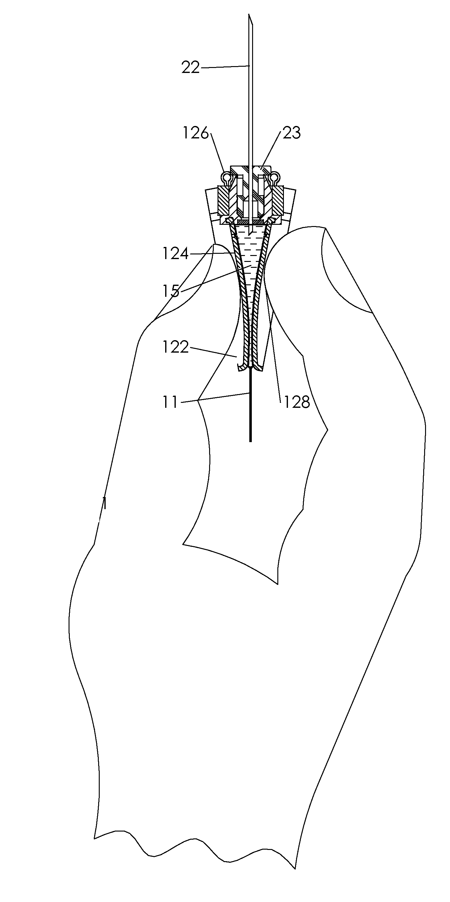
[0063]Referring now to FIGS. 13a-13f, a further preferred embodiment is demonstrated which is mostly similar to the embodiment 120 of FIG. 12, with the exception that an automatic piercing mechanism is incorporated in the needle protector. FIG. 13a, and its enlarged detail view in FIG. 13b, demonstrate the device 130 in the rest position A cylindrical sleeve 131 is accommodated concentric with the needle 22, and spaced apart from needle hub 23. The sleeve 131 is connected to two joint arms 132 at one end of the joint arms. The other end of the joint arms 132 are connected to the hoods 122, and at the rest positioned the arms are folded and confined between the sleeve 131 and the hoods 122. FIG. 13c, and its enlarged detail view in FIG. 13d, demonstrate the device 130 at intermediate instant of opening the hoods 122. The end of the arms 132 that are connected to the hoods 122 are pulled out with the hoods, causing the sleeve 131 to move toward, and get in contact with, the needle hub...
embodiment 170
[0073]FIGS. 18a-18e demonstrate embodiment 170 of FIG. 17 in the ready position. After the compartments 15 and 16 were merged and mixed by pressing and mashing the wall of the package 11 with a finger, the knob 172 is forced by pushing forward the compression panel 172″ with a finger to the forward position. FIG. 18a provides a general view of the device 170 with the needle 22 now extending from the housing 171 through opening 173. Normally at this position the needle is inserted to a target tissue of a patient, which is not shown here. FIG. 18b demonstrates a top view of the device 170 providing orientation for the subsequent section views. The grooves 188 in the upper wall of the housing in which the ribs 177 (not shown) of the knob 172 engage, are now visible. A widening portion of the groove 188 allows clearance for the pivots 179 to pass through the wall into the housing 171 during the assembly process.
[0074]Referring to FIG. 18c, at the front position of the knob 172, the teet...
embodiment 200
[0082]Referring now to FIG. 20 a further preferred embodiment 200 is demonstrated. The device 200 is mostly similar to the device 190 of FIG. 19 but for the different piercing means. The device 200 is demonstrated in the administration position. A u cut in the bottom wall of the housing 201 defines a cantilever section 202. To administer the content of compartment 15 one finger presses the compression panel 172″ while another finger provides for an opposite force on the cantilever section 202, such that the cantilever section 202 bends in and forces the proximal end of the needle 22″ to bend and pierce the wall of the first compartment 15. A sealing member 205 enhances the sealing of the wall of the well 186 of compartment 15. The sealing member 205 can be made of soft thermoplastic or rubber.
[0083]Referring now to FIGS. 21a-21h, a further preferred embodiment of the present invention is demonstrated. Referring to FIG. 21a a perspective view is showing the upper side of the device 2...
PUM
 Abstract
Description
Claims
Application Information
 - R&D
- Intellectual Property
- Life Sciences
- Materials
- Tech Scout
- Unparalleled Data Quality
- Higher Quality Content
- 60% Fewer Hallucinations
Browse by: Latest US Patents, China's latest patents, Technical Efficacy Thesaurus, Application Domain, Technology Topic, Popular Technical Reports.
© 2025 PatSnap. All rights reserved.Legal|Privacy policy|Modern Slavery Act Transparency Statement|Sitemap|About US| Contact US: help@patsnap.com


