
Electrical bushing for a superconductor element

a superconductor element and electric bushing technology, applied in the direction of cable fittings, connection contact member materials, electric cable installations, etc., can solve the problems of deterioration in the vacuum level in the intermediate enclosure, difficult and expensive manufacturing constraints, and additional consumption of liquid nitrogen, so as to improve the structure of the electrical bushing

Inactive Publication Date: 2009-07-02
NEXANS
View PDF3 Cites 17 Cited by
  • Summary
  • Abstract
  • Description
  • Claims
  • Application Information

AI Technical Summary

Benefits of technology

[0008]The present invention provides a solution to that technical problem, in particular by improving the structure of the electrical bushing.

Problems solved by technology

Nevertheless, a high electric current can lead to heat losses due to the conductor becoming heated by the Joule effect, and under such circumstances it is advantageous to increase the section of the central conductor.
Another technical problem to be solved is that of controlling the distribution of the electric field created by the medium or high voltage of the central conductor of the electrical bushing so as to avoid breakdowns.
The drawback of that solution lies in the need for good sealing of the intermediate enclosure, and in particular of the places where the electrical bushing passes through the bottom and top walls, thus leading to manufacturing constraints that are difficult and expensive.
For example, even a very small leak between the cryogenic temperature portion and the intermediate enclosure (e.g. a leak of about 10−8 millibars per liter second (mbar / L.s)) inevitably leads to a change in the composition of the gas or to a deterioration in the vacuum level in the intermediate enclosure.
If the cryogenic fluid is liquid nitrogen, a leak leads to the presence of gaseous nitrogen in the intermediate enclosure, thus leading firstly to additional consumption of liquid nitrogen, and secondly to a decrease in the thermal and electrical insulation of the intermediate enclosure.
Excess pressure in the intermediate enclosure as a result of such a leak is also unsuitable for being controlled by means of safety valves since opening a safety valve would lead to the destruction of the thermal and dielectric insulating medium (vacuum or gas).

Method used


Image

  • Electrical bushing for a superconductor element
  • Electrical bushing for a superconductor element
  • Electrical bushing for a superconductor element

Examples


Embodiment Construction

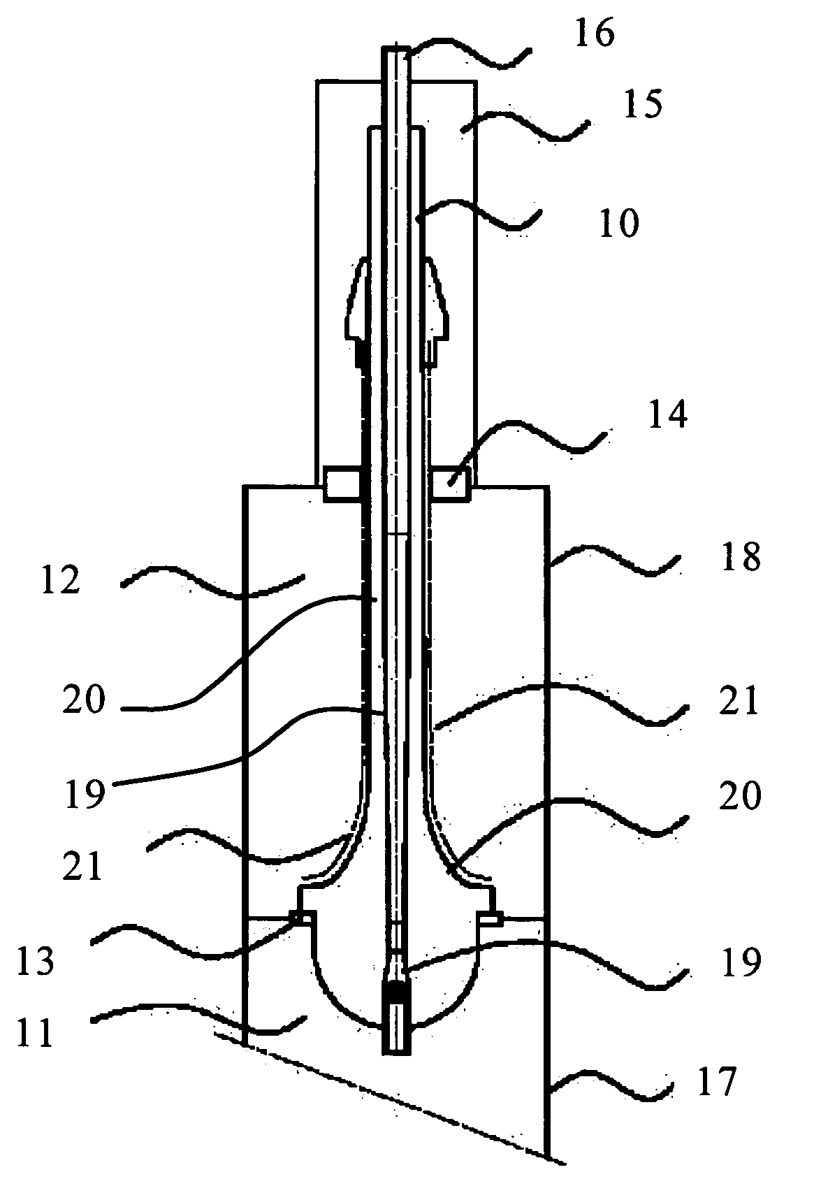
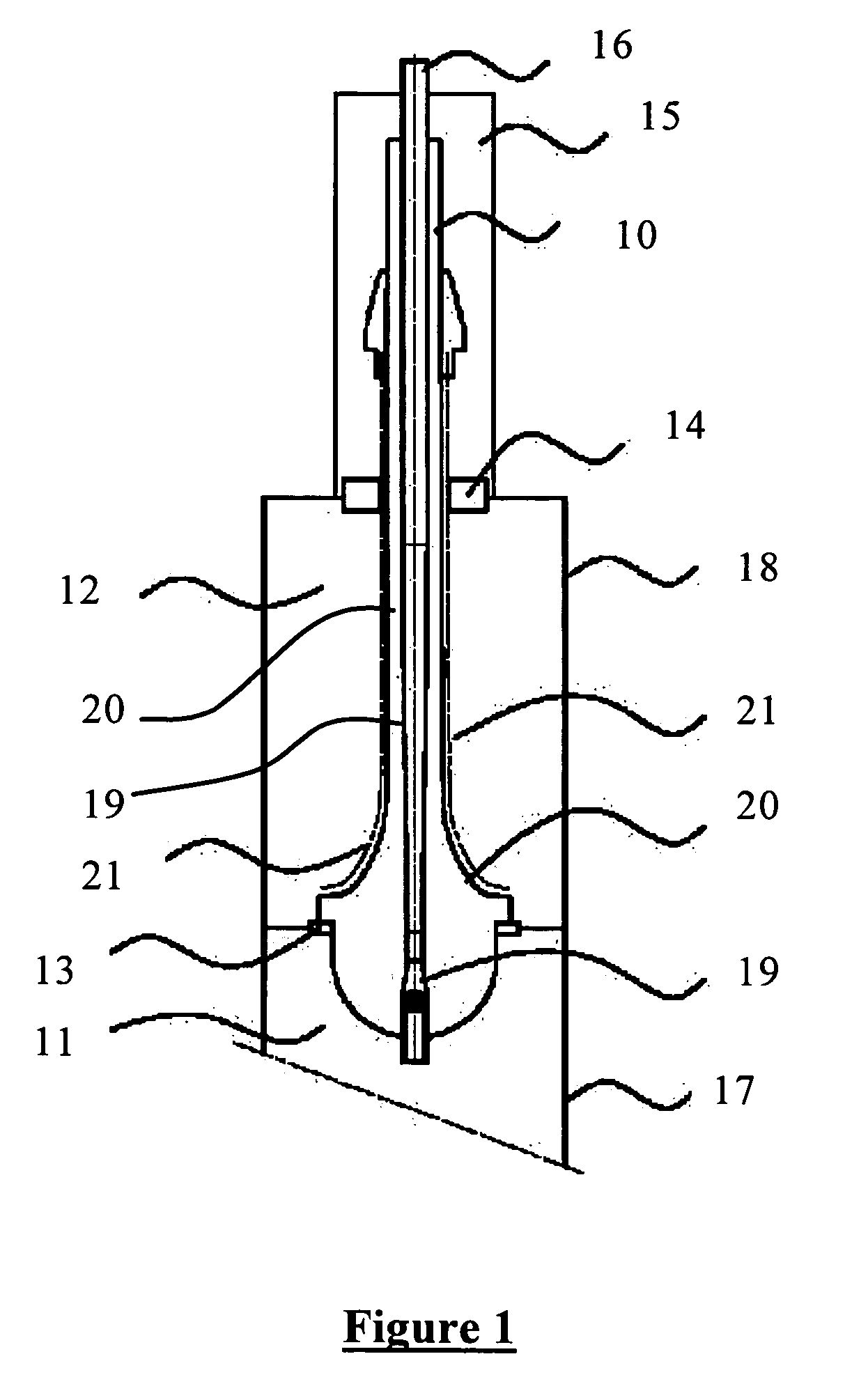
[0018]In FIG. 1, the connection structure to a superconductor cable (not shown) comprises an electrical bushing 10 connected to the superconductor element via its bottom end situated in an enclosure 11 at cryogenic temperature. An intermediate enclosure 12, adjacent to the cryogenic enclosure 11, is preferably filled with a solid material of low thermal conductivity. This material may be in the form of a foam, such as a polyurethane foam or a cellular glass foam, e.g. of the kind commercially available under the trademark Foamglas. The electrical bushing 10 passes through the bottom wall of the intermediate enclosure 11 via a leaktight fastening flange 13, and through the top wall via a leaktight fastening flange 14. The electrical bushing 10 is extended outside the intermediate enclosure 12 through an enclosure 15 at ambient temperature, and is terminated by means 16 for electrically connecting the bushing, and thus the superconductor element, to an appropriate device or equipment....


PUM


Abstract

The invention relates to an electrical bushing serving to make a connection at ambient temperature to a superconductor element situated in an enclosure at cryogenic temperature. The electrical bushing passes successively through an enclosure at intermediate temperature between ambient temperature and cryogenic temperature, and an enclosure at ambient temperature, and it comprises a central electrical conductor surrounded by an electrically insulating sheath. According to the invention, an electrically conductive screen connected to ground potential surrounds the insulating sheath over a section that extends from the end of the bushing that is in contact with the enclosure at cryogenic temperature at least as far as the junction between the enclosure at intermediate temperature and the enclosure at ambient temperature. The invention is more particularly applicable to making a connection to a superconductor cable.

Description

GOVERNMENT LICENSE RIGHTS[0001]This invention was made with government support under contract No. DE-FC36-00G013032 awarded by the Department of Energy (DOE). The government has certain rights in the invention.RELATED APPLICATION[0002]This application is related to and claims the benefit of priority from French Patent Application No. 05 50695, filed on Mar. 17, 2005, the entirety of which is incorporated herein by reference.FIELD OF THE INVENTION[0003]The present invention relates to an electrical bushing for a superconductor element, such as a cable for transporting electricity under medium or high voltage. The electrical bushing serves to connect the end of the superconductor element at cryogenic temperature to a device or equipment at ambient temperature, usually in the open air.BACKGROUND OF THE INVENTION[0004]Because of the large difference in temperature between the superconductor element and the equipment for connecting to said element, i.e. between ambient temperature and cr...

Claims


Application Information

Patent Timeline
IPC IPC(8): H02G3/18
CPCH01R4/68Y02E40/648H02G15/34Y02E40/60H01R4/58
Inventor MIREBEAU, PIERRELALLOUET, NICOLASDELPLACE, SEBASTIENLAPIERRE, REGIS
Owner NEXANS
Learn More