
Enhanced regas system

a regas system and regas technology, applied in water supply installations, gas/liquid distribution and storage, waterborne vessels, etc., can solve the problems of reducing the heat exchange capacity of the layer, affecting operation, and increasing the thickness of the layer, so as to reduce the cost, reduce the cost, and reduce the effect of fog

Inactive Publication Date: 2009-07-02
WIINDAARDEN WIM VAN +1
View PDF9 Cites 6 Cited by
  • Summary
  • Abstract
  • Description
  • Claims
  • Application Information

AI Technical Summary

Benefits of technology

"The present invention provides a method for heating liquefied gas at a final destination using low-cost and environmentally friendly methods. The heating is accomplished by vertically-extending air vaporizers, which vaporize the liquefied gas by using airflow. The air vaporizers are operated in a repetitive cycle of vaporizing and defrosting a limited number of vaporizers at a time. The invention is particularly suitable for large-scale applications such as LNG import terminals and floating offshore structures. The invention also includes a computerized CFD calculation method to predict the performance of a large number of vaporizers in close proximity to each other. The invention provides a simple and cost-effective system for heating liquefied gas, and can be enhanced by additional blowers and heating elements to defrost built-up ice layers and melt ice."

Problems solved by technology

The ice layer increases in thickness with the duration of the operation of the vaporizer, and thus reduces its capacity to exchange heat.
Also a large cloud of fog can be formed in windless or low wind conditions, which will affect operation in certain applications.

Method used


Image

  • Enhanced regas system
  • Enhanced regas system
  • Enhanced regas system

Examples


Embodiment Construction

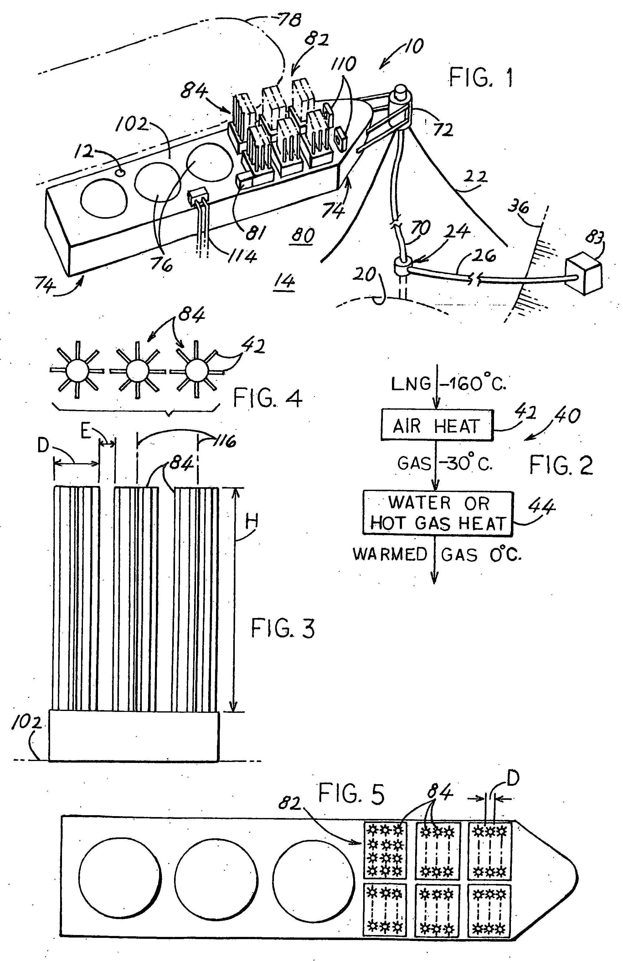
[0020]FIG. 1 illustrates an example of a floating import terminal 10 which includes a floating structure 74 (in the case of LNG the structure is also called FSRU, for Floating Storage and Regasification Unit) that has tanks 76 that store liquefied gas. Applicant uses the term “liquefied gas” to mean hydrocarbons that are gaseous at environmental temperatures (e.g. 15° C.) and pressures (e.g. one bar) and that have been cooled below −30° C. to liquefy the hydrocarbons. The floating structure 74 has an inlet 12 through which the liquefied gas is received from a liquefied gas tanker 78. The FSRU floating structure 74 typically stores a large quantity of thousands of tons of liquefied gas, with LNG (liquefied natural gas) maintained at a temperature such as −160° C. to keep it liquid at atmospheric pressure. The FSRU floating structure 74 is moored to the sea floor 14 at an offshore location 80, with a harbor shown.

[0021]The cold liquid hydrocarbon gas in the tanks 76 of the floating st...


PUM


Abstract

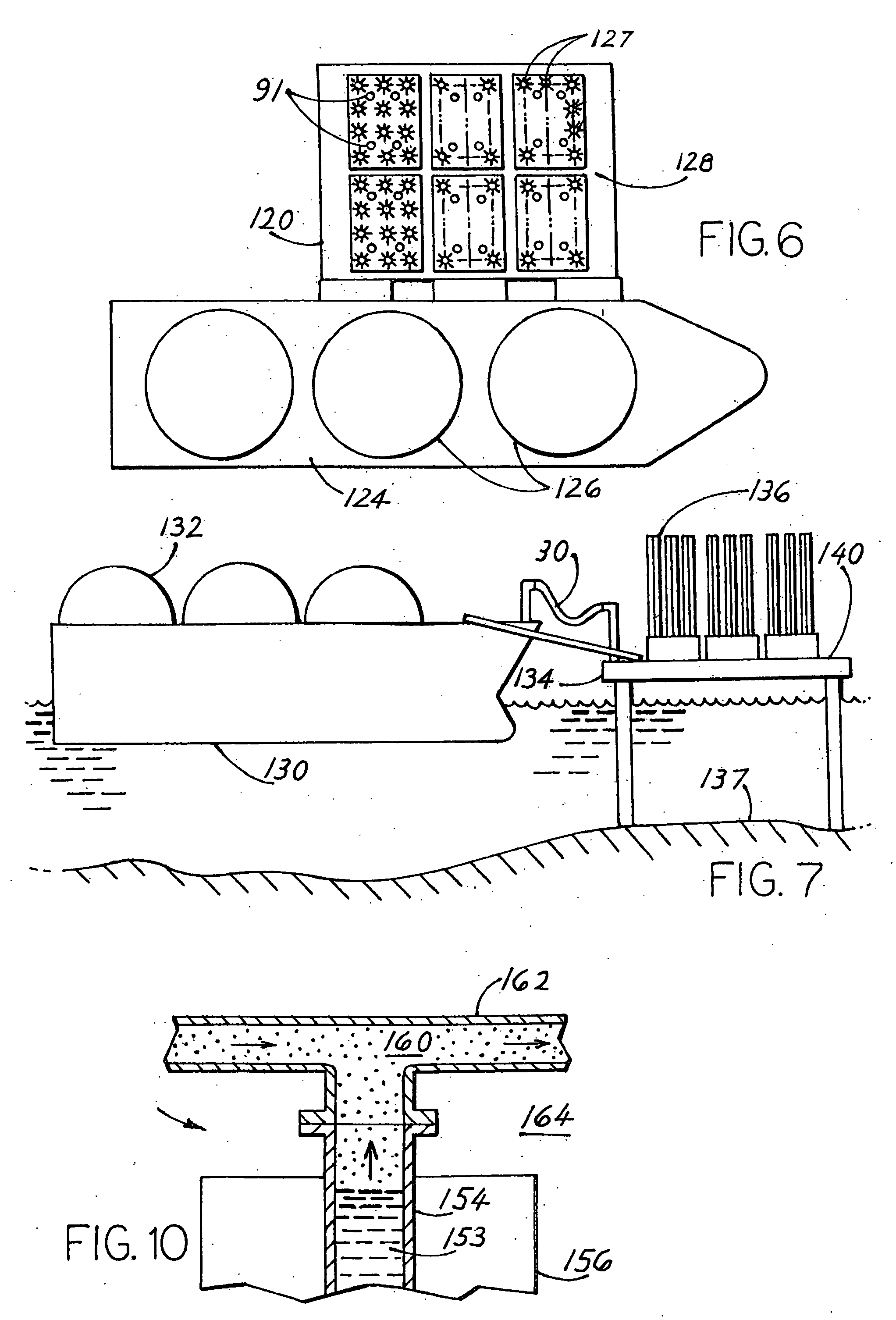
Liquefied hydrocarbon gas carried by a tanker (78) is transferred to an import terminal (10) where the liquefied gas is heated to vaporize it and to heat the cold gas to at least −30° C. but preferably about 0° C., with the warmed gas transferred to a gas receiving facility (20, 83). Vaporizing and heating is accomplished by using a large number (more than 10) of vertically mounted air vaporizers (84) of a known type, which use environmental air that flows down the exterior of the finned tubes in which the liquefied or cold gas flows. In the present invention a large number of individual vaporizers are positioned in close proximity to each other, i.e. within a distance that is smaller than half the vertical height of the vaporizer tubes. Their close proximity allows many units to be installed on a small plot space, and also affects their thermal performance.

Description

BACKGROUND OF THE INVENTION[0001]Gaseous hydrocarbons, which are hydrocarbons that are gaseous at mild environmental temperatures such as 15° C. and atmospheric pressure, are often transported great distances by tanker in liquid form (“liquefied gas”) as LNG (liquefied natural gas) such as LPG (liquefied petroleum gas, commonly containing primarily propane and butane). To keep LNG liquid at approximately atmospheric pressure, it is maintained at a low temperature such as −160° C. in highly thermally insulated tanks. At the tanker offloading destination, the LNG is offloaded to an import terminal where it is vaporized (heated to turn it into a gas) and warmed, and where the warmed gas is passed though a pipeline to users or stored.[0002]The heating of large quantities of liquefied gas can be done by flowing large quantities of seawater though a heat exchanger. However, such use of large quantities of seawater is not acceptable in many areas because large quantities of sea life such a...

Claims


Application Information

Patent Timeline
Patent Type & Authority Applications(United States)
IPC IPC(8): F17C9/02F17C13/08
CPCF17C5/06F17C2270/0136F17C2221/033F17C2223/0161F17C2223/033F17C2225/0123F17C2225/035F17C2227/0135F17C2227/0311F17C2227/0313F17C2227/0393F17C2260/032F17C2265/05F17C2270/0105F17C2270/0123F17C9/02Y10T137/8807
Inventor WIINDAARDEN, WIM VANUBAS, MATTHIEU
Owner WIINDAARDEN WIM VAN
Learn More