Wavelength division multiplexing transmission system

a transmission system and wavelength division technology, applied in the field of wavelength division multiplexing transmission systems, can solve the problems of transmission degradation, optical waveform distortion, and cannot serve as a universally applicable method for increasing transmission capacity, and achieve the effect of slow fluctuation and length of burst errors

Inactive Publication Date: 2009-06-25
FUJITSU LTD
View PDF8 Cites 29 Cited by
  • Summary
  • Abstract
  • Description
  • Claims
  • Application Information

AI Technical Summary

Benefits of technology

[0040]According to at least one embodiment, in a wavelength division multiplexing transmission system in which a channel using an intensity modulation scheme and a channel using a phase modulation scheme are present, a length of burst errors can be set shorter than an error correction frame period even in an environment in which a bit error rate exhibits extremely slow fluctuation due to an effect of the intensity-modulated channel on the phase-modulated channel. Further, the number of portions suffering no bust error in one error correction frame becomes two or more, which can prevent the occurrence of error-uncorrectable state and signal quality degradation.

Problems solved by technology

Such method thus cannot serve as a universally applicable method for increasing transmission capacity.
Here, nonlinear characteristics of an optical fiber cause transmission degradation.
Such phase modulation causes the optical spectrum to spread, resulting in the distortion of optical waveform due to the dispersion characteristics of the transmission fiber.
This phase modulation causes a distortion in the optical waveform due to the dispersion characteristics of the transmission fiber.
In such a case, the characteristics of the additional transponder may degrade due to interaction between the two transponders.
A risk of suffering degradation is rather high.
The worst polarization condition may last more than a few seconds to cause burst errors.
It is well known, however, that FEC cannot correct error if a poor error rate condition (i.e., a condition in which the error rate exceeds a correctable burst error rate) lasts more than a certain time period (e.g., the length of an FEC correction frame).
Under such circumstances, the error rate of the FEC output may not be improved, or may even be worse.
As previously described, error rate fluctuation occurs due to changes in relative polarization between two optical signals resulting from changes in the environmental conditions of a terminal equipment.
It is thus difficult to predict and control the error rate fluctuation.
This technology does not take into account a situation in which a channel is added to an existing optical terminal, and, thus, cannot obviate the problems described above.
This technology does not take into account the effect that XPM responsive to the optical intensity of an intensity-modulated channel has on another channel utilizing phase modulation, and, thus, cannot obviate the problems described above.

Method used


Image

  • Wavelength division multiplexing transmission system
  • Wavelength division multiplexing transmission system
  • Wavelength division multiplexing transmission system

Examples


first embodiment

[0055]FIG. 4 is a drawing showing an example of the configuration of a transmission side of a system according to a first embodiment.

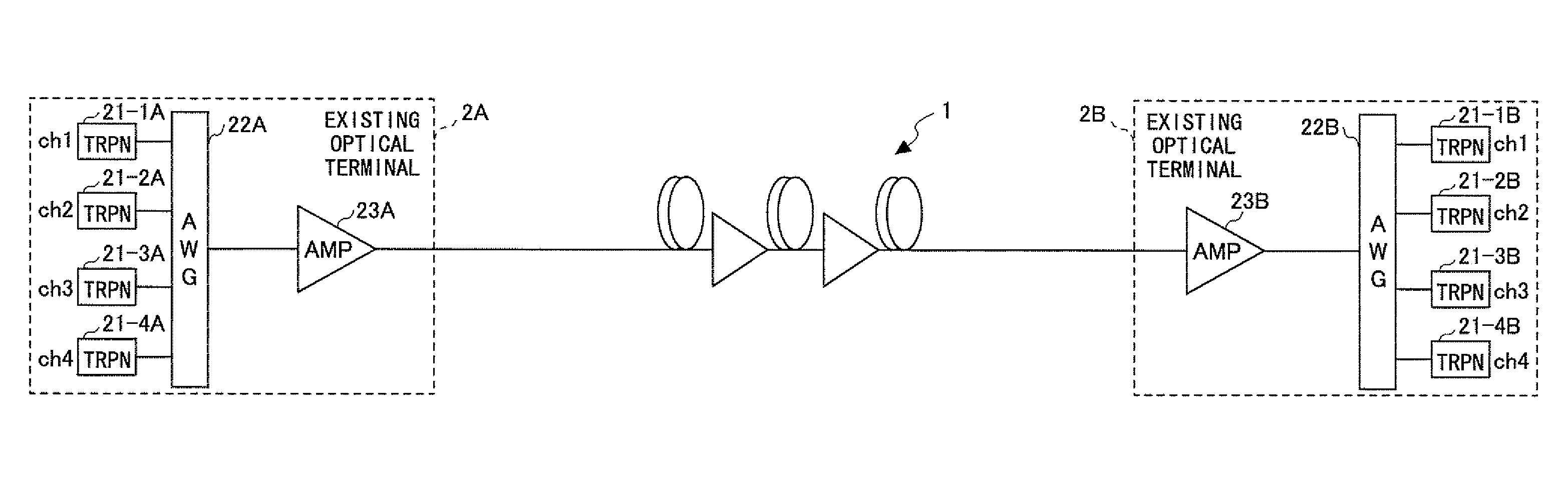
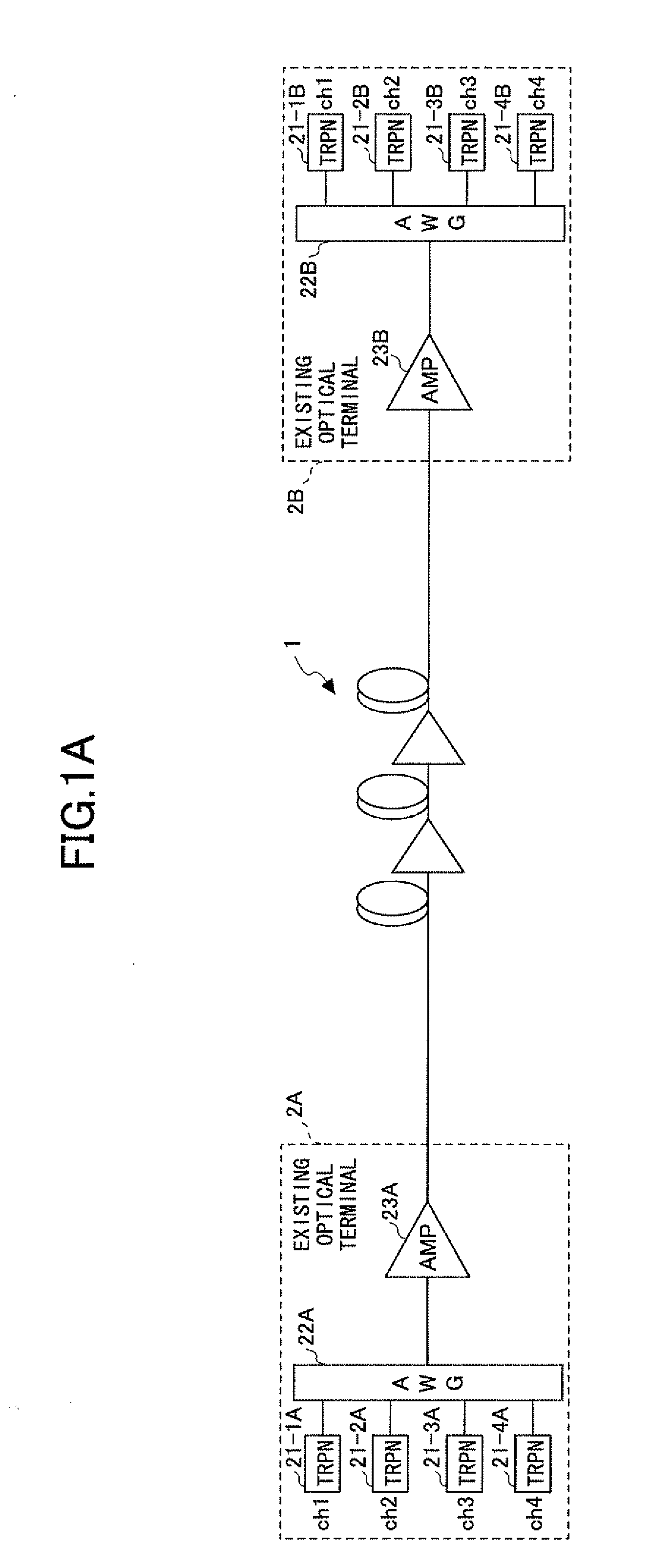
[0056]In FIG. 4, the configuration of the existing optical terminal 2A on the transmission side is the same as the configuration illustrated in FIG. 1B. Here, the existing channels ch1 through ch4 employ the intensity-modulated RZ-OOK scheme. The existing optical terminal 2B on the reception side also has a similar configuration.

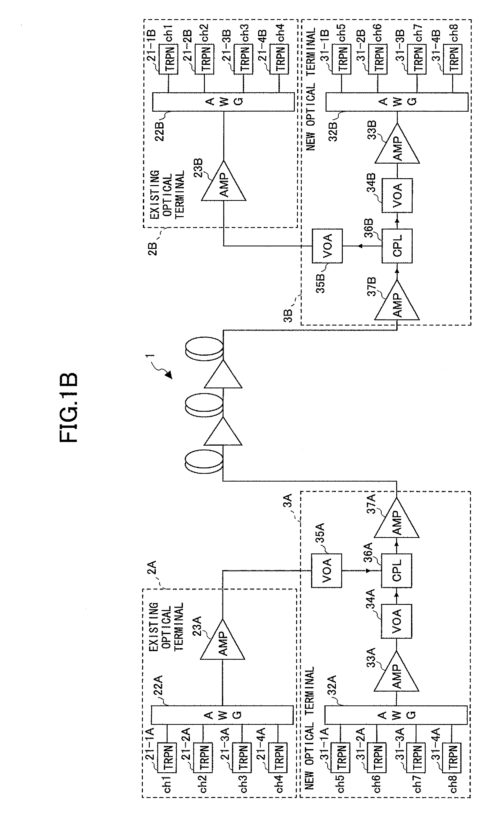
[0057]A new optical terminal 3A on the transmission side has new channels ch5 through ch8 employing the phase-modulated RZ-DPSK scheme. The relationships between these new channels and the existing channels ch1 through ch4 are supposed to be the same as those illustrated in FIG. 1C. The configuration of the new optical terminal 3A is similar to that illustrated in FIG. 1B, with a few differences. Such differences include the provision of polarization scramblers 301-2 and 301-3 immediately after the transponders 31-2A and 31-3A ...

second embodiment

[0064]FIG. 5 is a drawing showing an example of the configuration of a transmission side of a system according to a second embodiment. In this embodiment, a polarization scrambler is inserted into a path after multiplexing, rather than being provided separately for each of the new channels that suffers XPM from an adjacent existing channel. This configuration can provide the same result since the intended effect of polarization scrambling is attributable to changes in relative polarization between an intensity modulated signal and a phase modulated signal.

[0065]In FIG. 5, the optical outputs of the transponders 31-1A through 31-4A corresponding to the new channels ch5 through ch8 are directly supplied to the multiplexer / demultiplexer unit 32A. A polarization scrambler 301 is provided at the output of the optical amplifier 33A situated after the multiplexer / demultiplexer unit 32A. Configurations other than what is described above are the same as those in the first embodiment illustra...

third embodiment

[0070]The third embodiment is directed to a configuration in which the receiver unit of a transponder in the new optical terminal 3B on the reception side is configured to cope with polarization dependency. FIG. 6 is a drawing showing an example of the configuration of a receiver unit of a reception-side transponder using the RZ-DPSK scheme. A 1-bit delay optical interferometer is provided for an optical input to divide the output path according to “0 / 1” of the optical signal, and a pair of balanced photodiodes PD is used to receive light. The output of the balanced photodiodes PD is amplified for provision to a discrimination and recovery circuit. The 1-bit delay optical interferometer is generally implemented by use of a thin optical waveguide formed on a substrate. The waveguide characteristics may vary depending on the polarization of incident light. Consequently, the level of the light received by the balanced photodiodes may be affected by the presence of polarization scrambli...


PUM


Abstract

A wavelength division multiplexing transmission system in which a first channel using an intensity modulation scheme and a second channel using a phase modulation scheme are present includes a polarization scrambler inserted into a signal path of either one of the first channel and the second channel to perform polarization scrambling, and a drive unit configured to drive the polarization scrambler at frequency greater than or equal to a value defined as: (bit rate of phase modulated signal)/(error correction frame length)×2.

Description

CROSS-REFERENCE TO RELATED APPLICATIONS[0001]The present application is based upon and claims the benefit of priority from the prior Japanese Patent Application No. 2007-327229 filed on Dec. 19, 2007, with the Japanese Patent Office, the entire contents of which are incorporated herein by reference.BACKGROUND OF THE INVENTION[0002]1. Field of the Invention[0003]The disclosures herein relate to a technology for providing additional channels in a WDM (wavelength division multiplexing) transmission apparatus.[0004]2. Description of the Related Art[0005]There is a demand for an increase in the transmission capacity of a submarine optical cable system in response to an increase in communication traffic. Generally, countermeasures as follows may be taken to meet such demand.[0006]A new submarine optical cable is laid down, and a submarine line terminal is constructed.[0007]A new submarine line terminal is added to a submarine optical cable that is laid down but unused (generally referred ...

Claims


Application Information

Patent Timeline
Patent Type & Authority Applications(United States)
IPC IPC(8): H04J14/00H04J14/02H04B10/2507H04B10/07H04B10/2557H04B10/516H04B10/54H04B10/548H04B10/58H04B10/61
CPCH04B10/2569H04J14/06H04J14/0221H04B10/532
Inventor NAKAMOTO, HIROSHI
Owner FUJITSU LTD
Why Eureka
Try Eureka