
Fire rated downlights

a technology of downlighters and downlights, which is applied in the direction of light fastenings, lighting heating/cooling arrangements, protective devices for lighting, etc., can solve the problems of compromising the integrity of the ceiling and/or roof space, compromising the ability of the ceiling to contain a fire in a room, and compromising the flow of air through the downlighter, so as to improve the fire rating of the downlighter, enhance the fire barrier properties, and improve clearance

Inactive Publication Date: 2009-06-25
GIGAPHOTON
View PDF15 Cites 8 Cited by
  • Summary
  • Abstract
  • Description
  • Claims
  • Application Information

AI Technical Summary

Benefits of technology

[0007]The provision of the intumescent material as a sleeve or lining of the internal tubular wall of the tubular body of the casing rather than as an end wall covering has been found to provide an efficient way of improving the fire rating of the downlighter and contrary to what was otherwise expected, not inherently vulnerable to triggering of the intumescent material to expand by its proximity to the lamp.
[0008]In the preferred arrangement the intumescent material is formed as a 1 or 2 mm thick sheet and is located within the tubular body as a liner extending substantially from the end wall or proximate thereto toward the front of the casing but suitably terminating short of the front of the casing. In a first preferred embodiment the intumescent material terminates at least 2 cm and preferably of the order of 5 cm short of the front end of the casing to improve clearance from the halogen lamp body 2 that is installed in use in the casing where the lamp body is tapered and the front face of the lamp is substantially level with the front end of the casing. This generally provides adequate clearance of the intumescent material from the lamp.
[0009]Unlike the prior art arrangements, the arrangement of the present invention provides for much greater filling of the void within the casing to enhance the fire barrier properties. The end wall of the casing body may even be free of any intumescent material and does not necessarily need to be blanked off by an intumescent material sheet placed against it. The present invention thus substantially improves airflow and, unlike the prior art, allows the use of dichroic reflector lamps within these casings

Problems solved by technology

Downlighters that are adapted to be installed into ceiling and / or roof spaces are inherently at risk of compromising the integrity of the ceiling and / or roof space.
They are generally installed into an aperture in the ceiling that has to be relatively wide to accommodate the downlighter assembly and thereby compromises the ability of the ceiling to contain a fire in a room or even a fire caused by the light fitting itself failing.
However, the positioning of a layer of intumescent material at the end of a downlighter assembly may compromise the flow of air through the downlighter.
This can cause excessive heat to build up during operation.
Firstly, bulb life may be significantly reduced and secondly, the intumescent material may be triggered to expand because of the excessive heat resulting from continuous running of the bulb.
Further drawbacks of this prior art include that they need to be used only with aluminium reflector lamps, being incompatible for use with the popular dichroic reflector lamps since these latter direct the heat from the lamp rearwardly and which would cause excessive heat build up inside the casing reducing lamp life and risking premature activation of the intumescent material.

Method used


Image

  • Fire rated downlights
  • Fire rated downlights
  • Fire rated downlights

Examples


Embodiment Construction

[0021]The present invention will now be described by way of example only. These are not the only ways that the invention may be put into practice but they are the best ways currently known to the applicant.

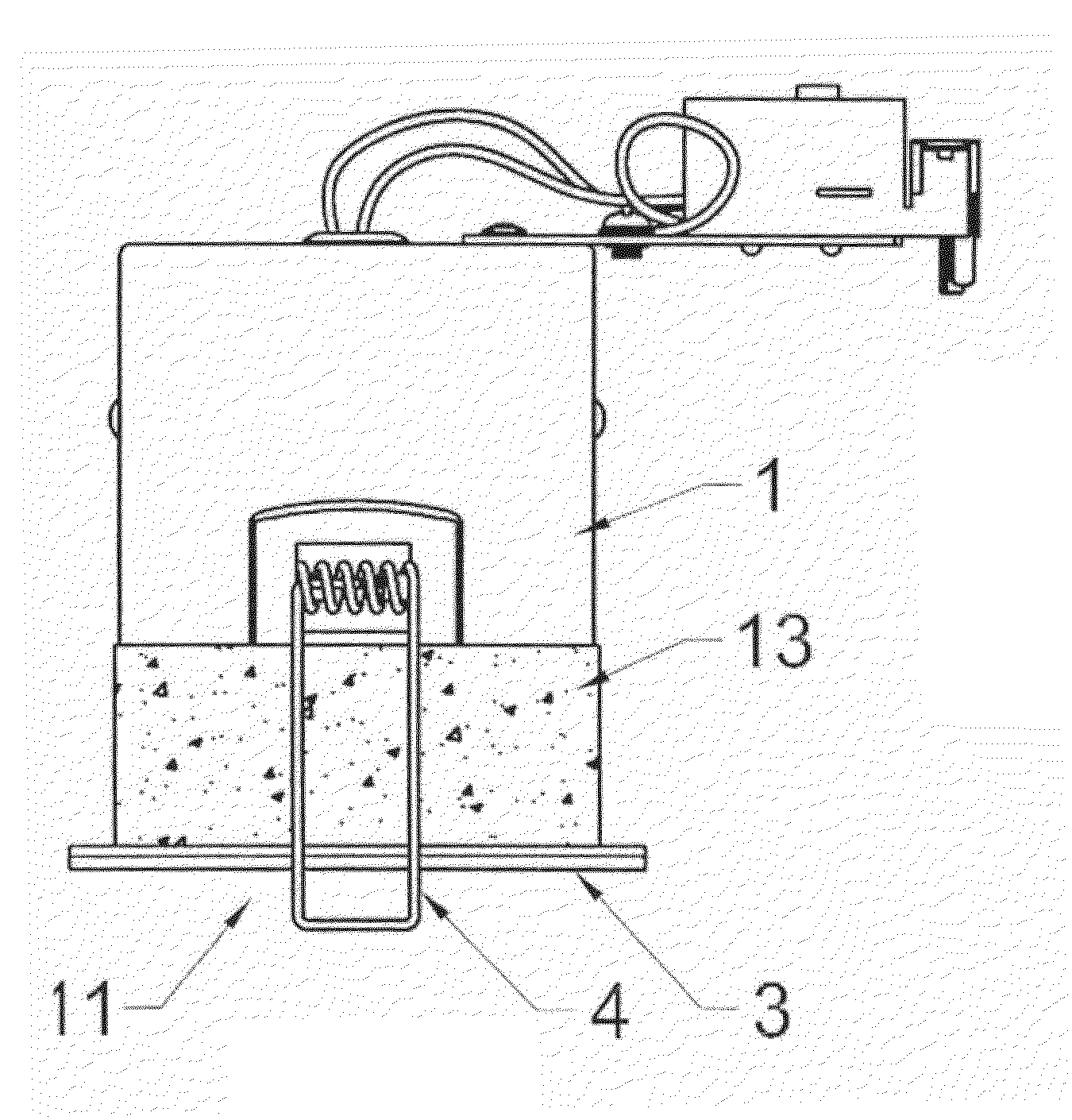
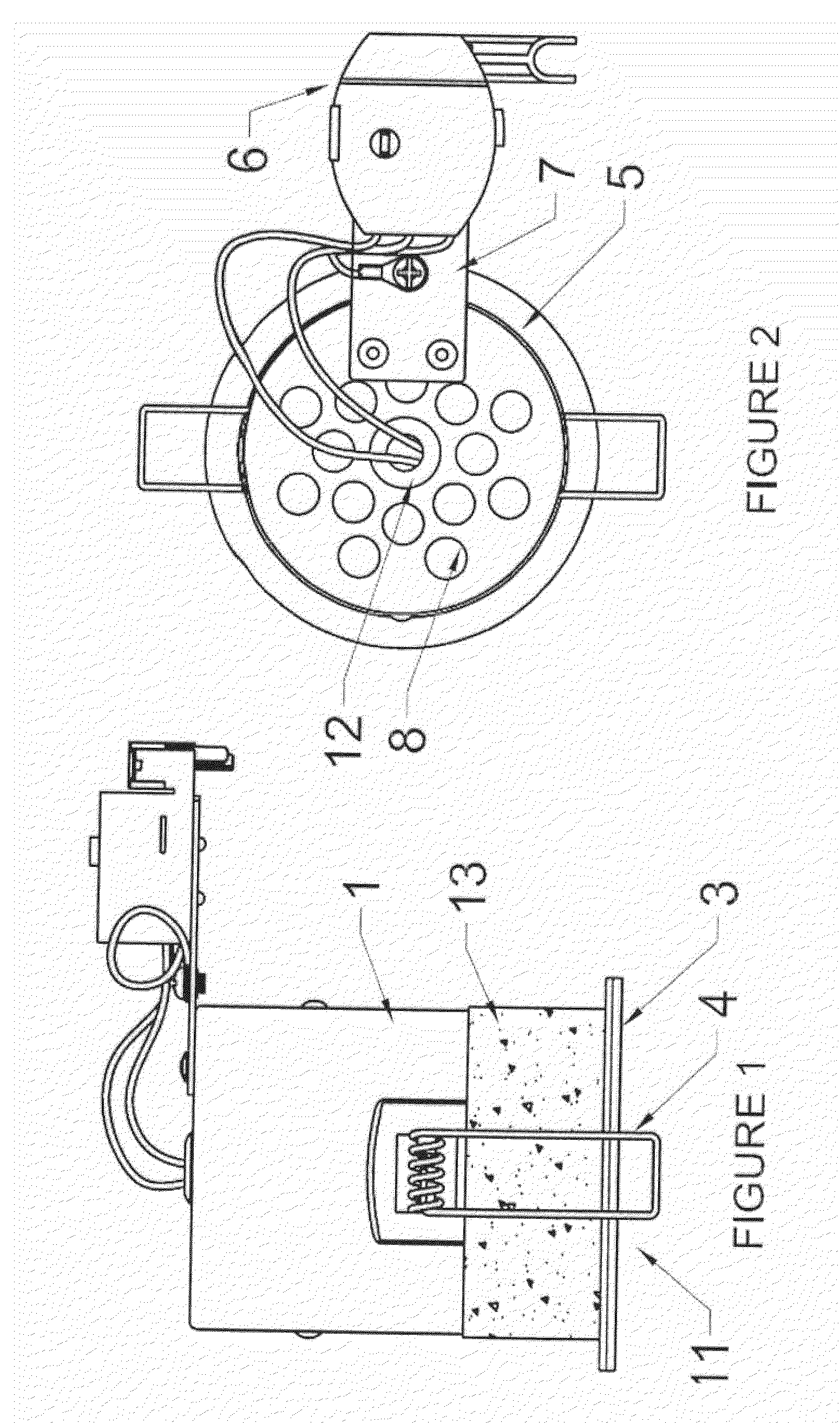
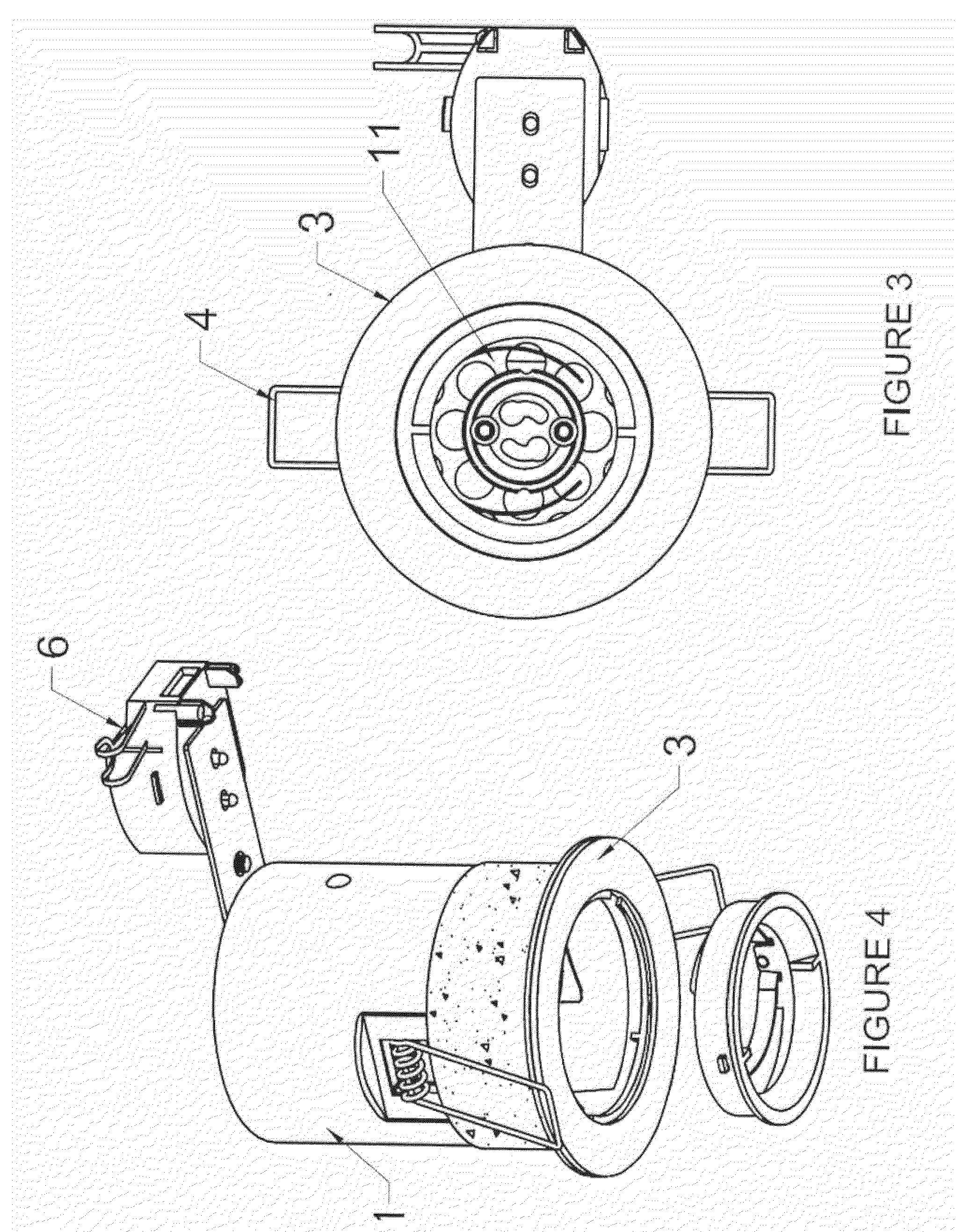
[0022]Referring to FIGS. 1 to 5, the downlighter assembly shown is relatively conventional in so far as it comprises a circular cylindrical casing 1 that is adapted to house a downlight lamp such as a halogen lamp 2 (illustrated here schematically in FIG. 5) and having an annular front flange 3 to butt up against the rim of the ceiling aperture in which the downlighter is being installed. A pair of resiliency sprung mounting clips 4 project laterally from either side of the casing 1 and are forwardly biased to press against the inner / upper surface of the ceiling to hold the casing 1 in place.

[0023]The circular cylindrical casing 1 resembles a canister with a rear end wall 5 and an open front end 11 through which the light from the lamp is projected directly or through a window.

[00...


PUM


Abstract

A casing for a downlight having a tubular body from which the light of a lamp when installed in the body is emitted from the front of the body and having a rear end wall closing the body from the rear, wherein intumescent material is placed within the tubular body lining the tubular wall of the tubular body.

Description

FIELD OF THE INVENTION[0001]The present invention concerns improvements in and relating to fire rated downlights.BACKGROUND TO THE INVENTION[0002]Downlighters that are adapted to be installed into ceiling and / or roof spaces are inherently at risk of compromising the integrity of the ceiling and / or roof space. They are generally installed into an aperture in the ceiling that has to be relatively wide to accommodate the downlighter assembly and thereby compromises the ability of the ceiling to contain a fire in a room or even a fire caused by the light fitting itself failing. In order to compensate against these increased risks, it is generally required that downlighters incorporate adaptations to improve their fire barrier capabilities and which generally include the provision of intumescent materials associated with the downlighter assembly and which expend in the heat of fire to occlude the openings defined by the downlighter.[0003]Since downlights generate a substantial amount of ...

Claims


Application Information

Patent Timeline
Patent Type & Authority Applications(United States)
IPC IPC(8): F21V29/00F21V15/00F21S8/02F21V25/00F21V29/15
CPCF21S8/02F21V25/00F21S8/026A62C3/16F21V21/04F21V25/12
Inventor JOHNSON, ANDREW JOSEPH
Owner GIGAPHOTON
Learn More