Heating apparatus

a heating apparatus and heat resistance technology, applied in the direction of ohmic-resistance heating, electrical apparatus, hot plate heating arrangement, etc., can solve the problems of limiting the temperature at which the heating apparatus can be used, limiting the uniform heating and maintaining of the wafer at the heated temperature, and low heat resistance of silicon resin

Inactive Publication Date: 2009-06-25
NGK INSULATORS LTD
View PDF12 Cites 90 Cited by
  • Summary
  • Abstract
  • Description
  • Claims
  • Application Information

AI Technical Summary

Benefits of technology

[0010]A heating apparatus has a heating surface on which a substrate is set, a base composed of a ceramic, a heating body embedded in the base; a heat conductive member provided between the heating surface of the base and the heating body and having a thermal conductivity higher than a thermal conductivity of the base, and a temperature adjusting member provided proximal to a back surface of the base. An air gap is provided between the base and the temperature adjusting member, and is connectable to a gas introduction apparatus which introduces a gas to the gap while adjusting a gas pressure in the gap.

Problems solved by technology

However, silicone resin has a low heat resistance, and thus limits the temperature at which the heating apparatus can be used.
Furthermore, due to a poor thermal conductivity of silicone resin, there is a limitation in uniformly heating and maintaining the wafer at the heated temperature.
However, even in such heating apparatus, sufficient uniformity of the heating temperature in the heating surface of the ceramic base cannot always be obtained.
The heating uniformity (thermal uniformity) is deteriorated particularly when the heat input to the resistance heating body is increased, or when the ceramic base is composed of a material having low thermal conductivity Accordingly uniformity is also deteriorated in the surface temperature of the wafer heated by such heating apparatus.
As a result, the production yield of the semiconductor device is reduced.

Method used


Image

  • Heating apparatus
  • Heating apparatus
  • Heating apparatus

Examples


example

1. Evaluation of the Heat Conductive Member 14

[0055]Firstly the thermal uniformity was evaluated using various types of the heat conductive member 14.

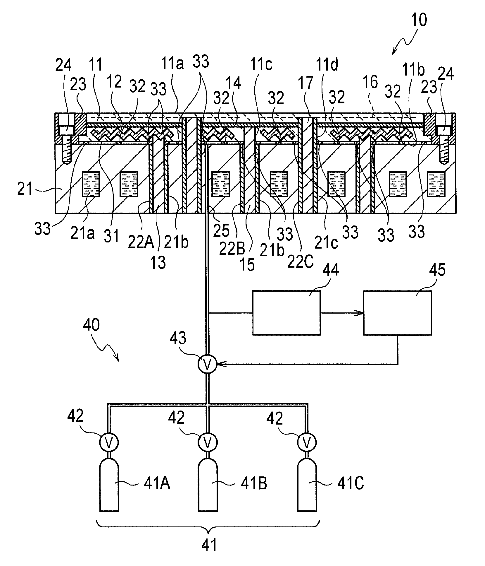
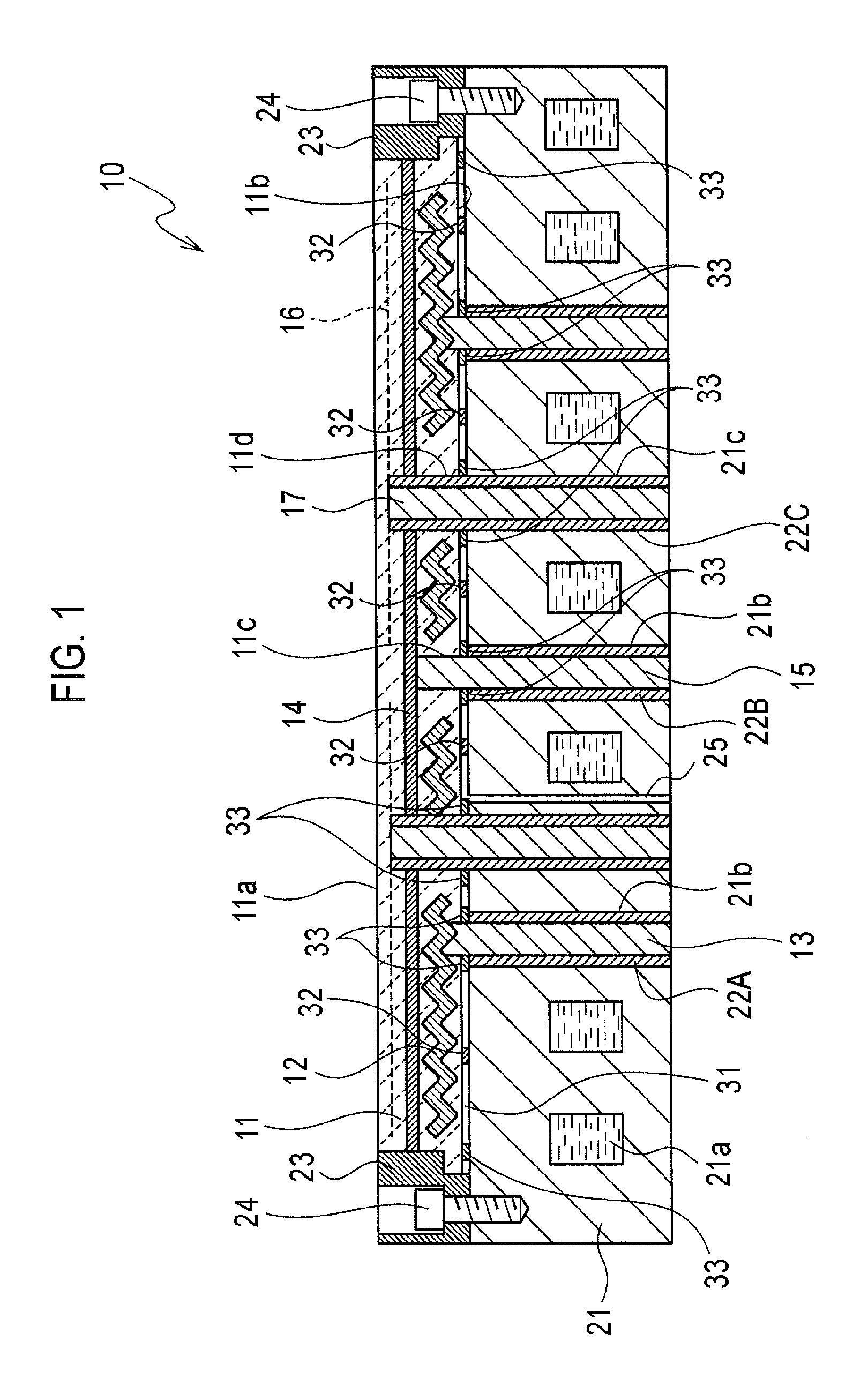
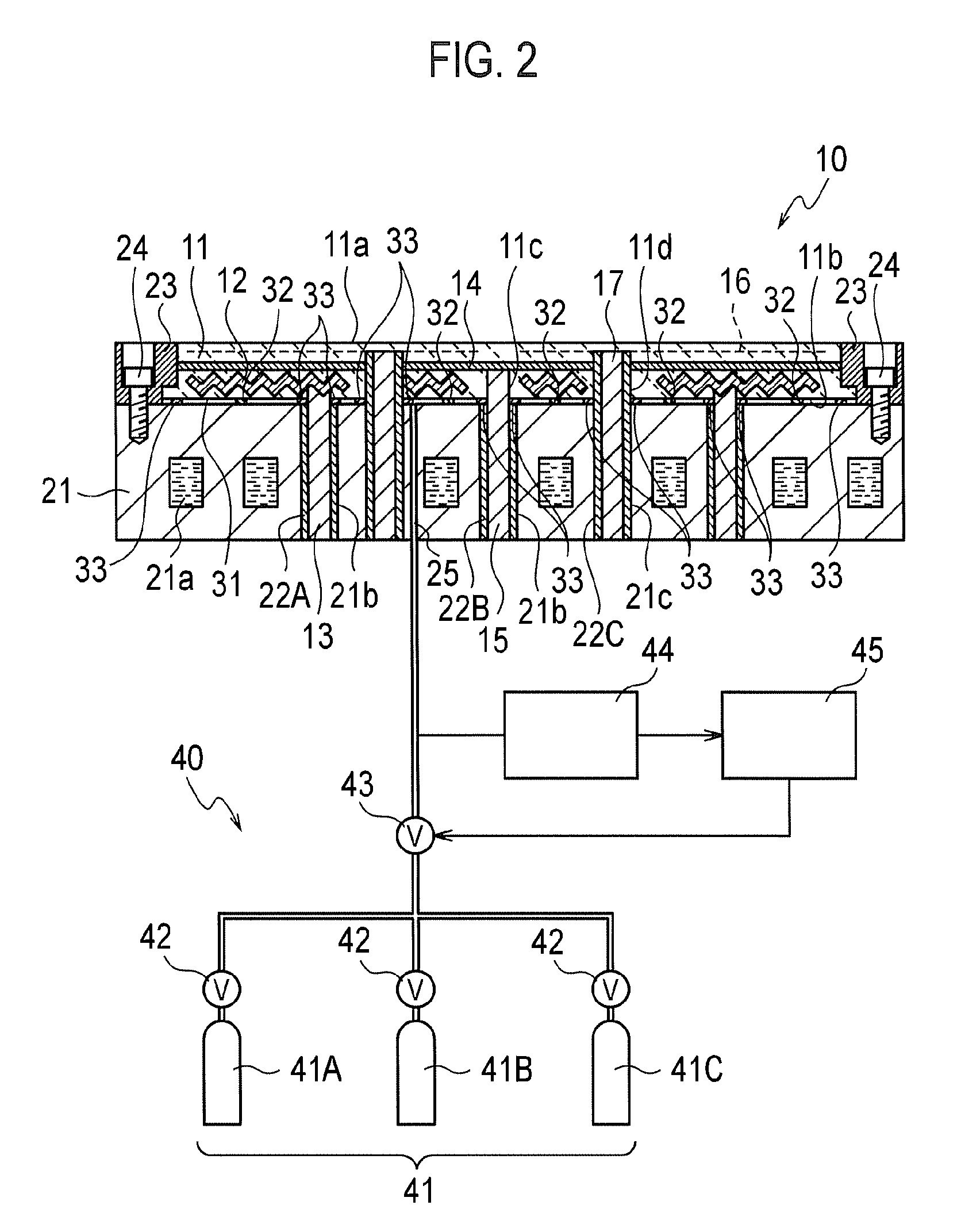
[0056]A ceramic sintered body serving as the upper portion of the ceramic base 11, a ceramic sintered body serving as the lower portion of the ceramic base 11, and the heat conductive member 14 were prepared.

[0057]A ceramic sintered body serving as the upper portion of the ceramic base 11 with an embedded electrostatic electrode was obtained in the following manner. A compact was formed from a raw material powder by means of press molding at the predetermined pressure using a mold, and then the compact was sintered by use of a hot press sintering method. A ceramic sintered body serving as the lower portion of the ceramic base 11 with an embedded resistance heating body was also obtained in the following manner. A compact was formed from a raw material powder by means of press molding at the predetermined pressure using a mold, and then...


PUM

PropertyMeasurementUnit
thicknessaaaaaaaaaa
thermal conductivityaaaaaaaaaa
thicknessaaaaaaaaaa

Abstract

A heating apparatus 10 includes a ceramic base 11 having a heating surface 11a and provided with a resistance heating body 12 embedded therein, and a temperature adjusting member 21 fixedly fastened proximal to a back surface of the ceramic base 11. A heat conductive member 14 having a thermal conductivity higher than the ceramic base 11 is provided between the heating surface of the ceramic base 11 and the resistance heating body 12. A gas is introduced to an air gap 31 between the ceramic base 11 and the temperature adjusting member 21 while controlling the gas pressure.

Description

CROSS REFERENCE TO RELATED APPLICATIONS[0001]This application is based upon and claims the benefit of priority from Japanese Patent Application No. 2007-234485, filed on Sep. 10, 2007; the entire contents of which are incorporated herein by reference.BACKGROUND OF THE INVENTION[0002]1. Field of the Invention[0003]The present invention relates to a heating apparatus, which is used for heating a semiconductor wafer and the like.[0004]2. Description of the Related Art[0005]In a process of manufacturing a semiconductor device, a heating process is performed to form an oxide film and the like on a wafer by using a semiconductor manufacturing device. A heating apparatus provided with a disk-shaped ceramic base is an example of the heating apparatus used for performing the wafer-heating process. The disk-shaped ceramic base has a heating surface on which a wafer is set, and has a resistance heating body embedded therein. The resistance heating body of the heating apparatus, which is embedd...

Claims


Application Information

Patent Timeline
Patent Type & Authority Applications(United States)
IPC IPC(8): H05B3/68
CPCH01L21/67103H01L21/683
Inventor MORIOKA, IKUHISATSURUTA, HIDEYOSHIAIHARA, YASUFUMI
Owner NGK INSULATORS LTD
Why Eureka
Try Eureka