
System for manufacturing linear gear and the method thereof

Inactive Publication Date: 2009-06-25
ILJIN LIGHT METAL CO LTD
View PDF4 Cites 5 Cited by
  • Summary
  • Abstract
  • Description
  • Claims
  • Application Information

AI Technical Summary

Benefits of technology

[0014]According to the present invention, a rack gear can be manufactured without limitation in the length of a teeth portion and the shape of the teeth.
[0015]In addition, extension of the service life of a rack gear can be achieved by applying weak impact and lower load to the linear bar when manufactured.
[0016]Furthermore, a rack gear of higher precision can be manufactured, thereby minimizing material loss and time required for manufacturing the rack gear.

Problems solved by technology

However, these conventional methods embrace many problems due to high-cost and lower efficiency.
In machining a rack gear having a non-regular pitch, a technology with high precision is required, and a high cost and extended process time are disadvantageously demanded as well.
Furthermore, the technique has drawbacks that distortion occurs quite often during plastic deformation and brittleness of the rack gear increases by instantaneously applying a high load deformation to the linear bar.

Method used


Image

  • System for manufacturing linear gear and the method thereof
  • System for manufacturing linear gear and the method thereof
  • System for manufacturing linear gear and the method thereof

Examples


Embodiment Construction

[0035]Hereinafter, preferred embodiments of the present invention will be explained in detail with reference to the accompanying drawings. Before explaining the invention, the terms and words used in the description and claims is not to be limited to ordinary meanings or dictionary definitions. Under the principles that the inventors are entitled to act as his or her own lexicographer in order to explain his or her own invention in the best way, those terms and words are to be construed so as to conform to the technical concept of the present invention.

[0036]The constructions disclosed in the specification and drawings show one preferred embodiment of the invention, not represent all the technical concepts of the invention. It is therefore understood that at the time of filing this application, various alternatives and modifications to these constructions may occur to those skilled in the art.

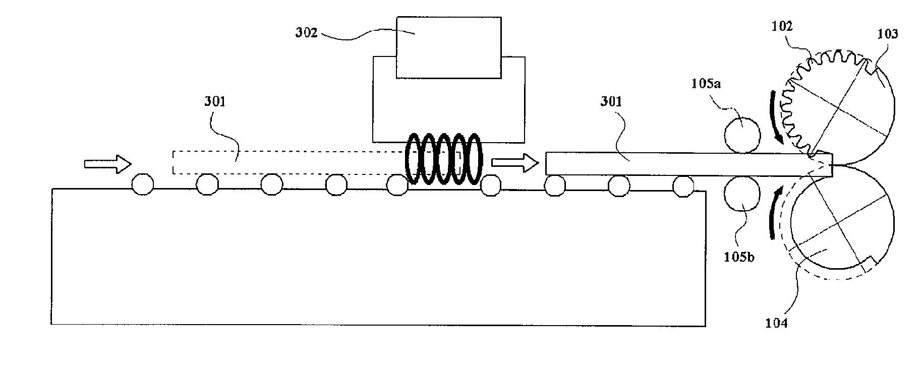
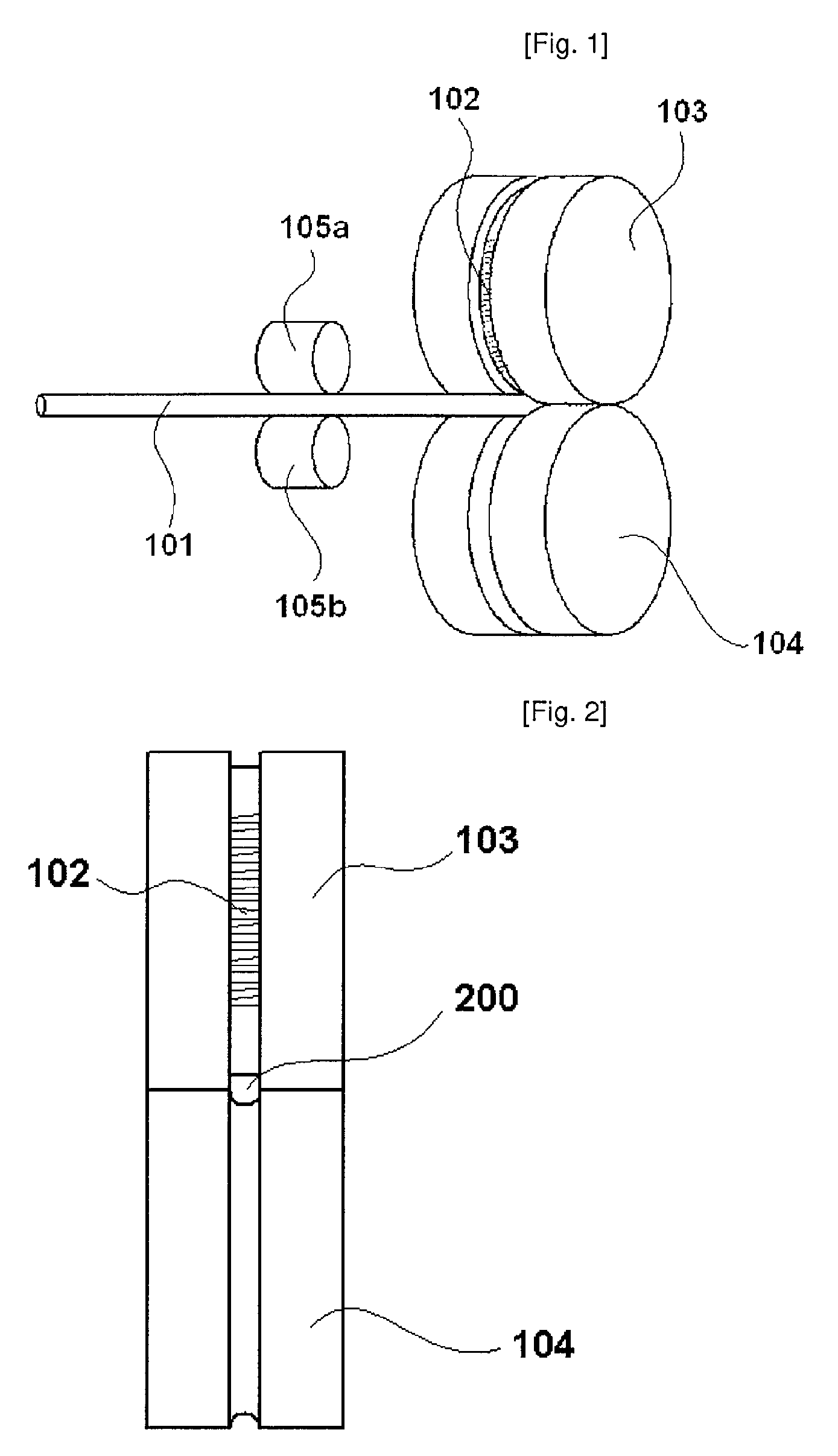
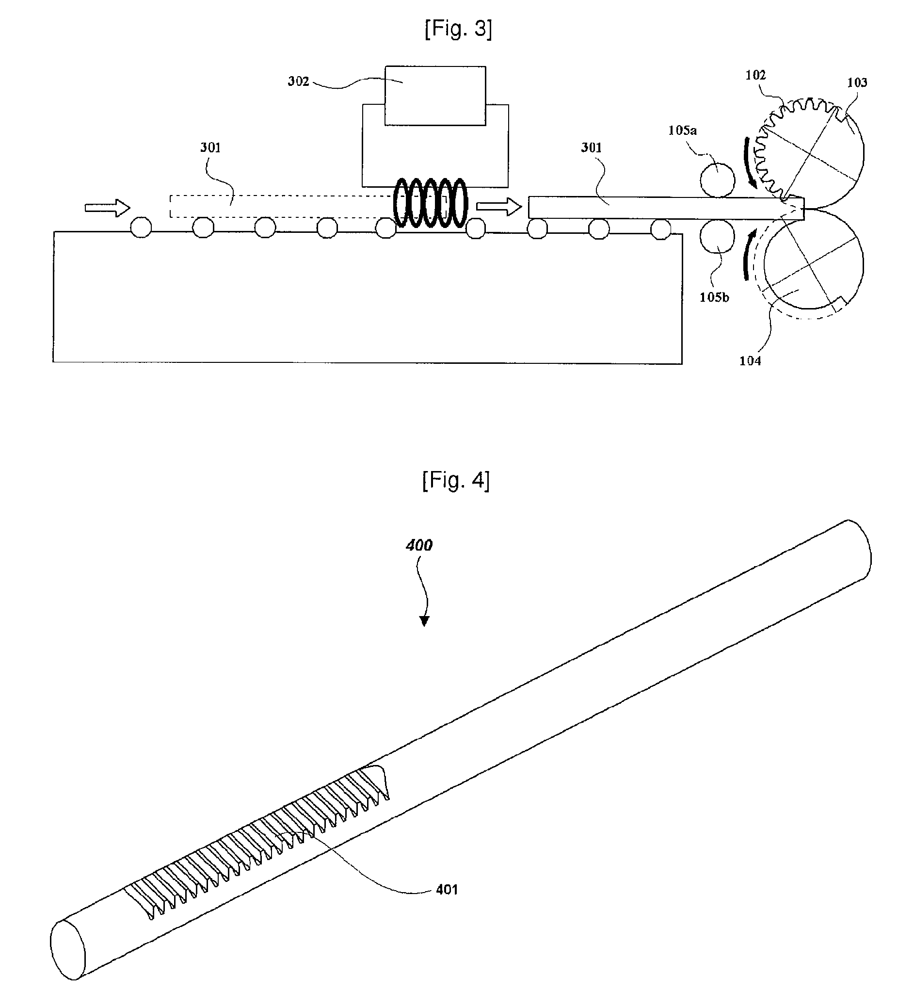
[0037]FIG. 1 is a perspective view showing a system for manufacturing a rack gear according...


PUM

PropertyMeasurementUnit
Temperatureaaaaaaaaaa
Fractionaaaaaaaaaa

Abstract

The present invention relates to a system for and a method of manufacturing a linear gear (rack gear), in which a forming roll and a guide roll are used to form gear teeth in a sequential manner so as not to require a high load, thereby enabling to easily manufacture the rack gear. A system for manufacturing a rack gear according to the invention includes a forming roll having a convexo-concave portion formed on a part of the surface contacting with a linear bar, a guide roll adapted to roll while facing the forming roll, and at least one support member for supporting the linear bar so as to allow the linear bar to linearly move. A method of manufacturing a rack gear according to the invention includes a first step of passing a linear bar through between a pair of rollers provided in front of a forming roll and a guide roll, a second step of charging the linear bar into a charging hole between the forming roll and the guide roll, a third step of rolling the forming roll and the guide roll to partly form teeth on the outer circumferential surface of the linear bar, and a fourth step of rolling the forming roll and the guide roll forward or backward to discharge the linear bar.

Description

TECHNICAL FIELD[0001]The present invention relates to a system for and a method of manufacturing a linear gear (hereinafter rack gear) by plastic deformation of a linear bar using a forming roll with a convexo-concave portion and a guide roll supporting the linear bar.BACKGROUND ART[0002]In the conventional rack gear manufacturing techniques, one lateral side of a rack gear is machined in a regular pitch to form a teeth portion. However, these conventional methods embrace many problems due to high-cost and lower efficiency.[0003]On the other hand, recently a liner gear of non-regular pitch has been used and a variable gear ratio (VGR) has been applied. In machining a rack gear having a non-regular pitch, a technology with high precision is required, and a high cost and extended process time are disadvantageously demanded as well.[0004]In recent years, therefore, a forging method has been used to form the teeth of a rack gear in order to mitigate the demerits in the machining techniq...

Claims


Application Information

Patent Timeline
IPC IPC(8): B21D37/16B21K1/30
CPCB21H5/00Y10T29/49467B21K1/767B21K1/00
Inventor JUNG, HEE-WONPARK, YOUNG-JUNEYEOM, GIL-YONGKIM, DONG-SAMLEE, JUNG-SU
Owner ILJIN LIGHT METAL CO LTD
Learn More