
Linkage coupling apparatus

Inactive Publication Date: 2012-05-03
MCCLELLAND KENNETH RAE
View PDF6 Cites 5 Cited by
  • Summary
  • Abstract
  • Description
  • Claims
  • Application Information

AI Technical Summary

Benefits of technology

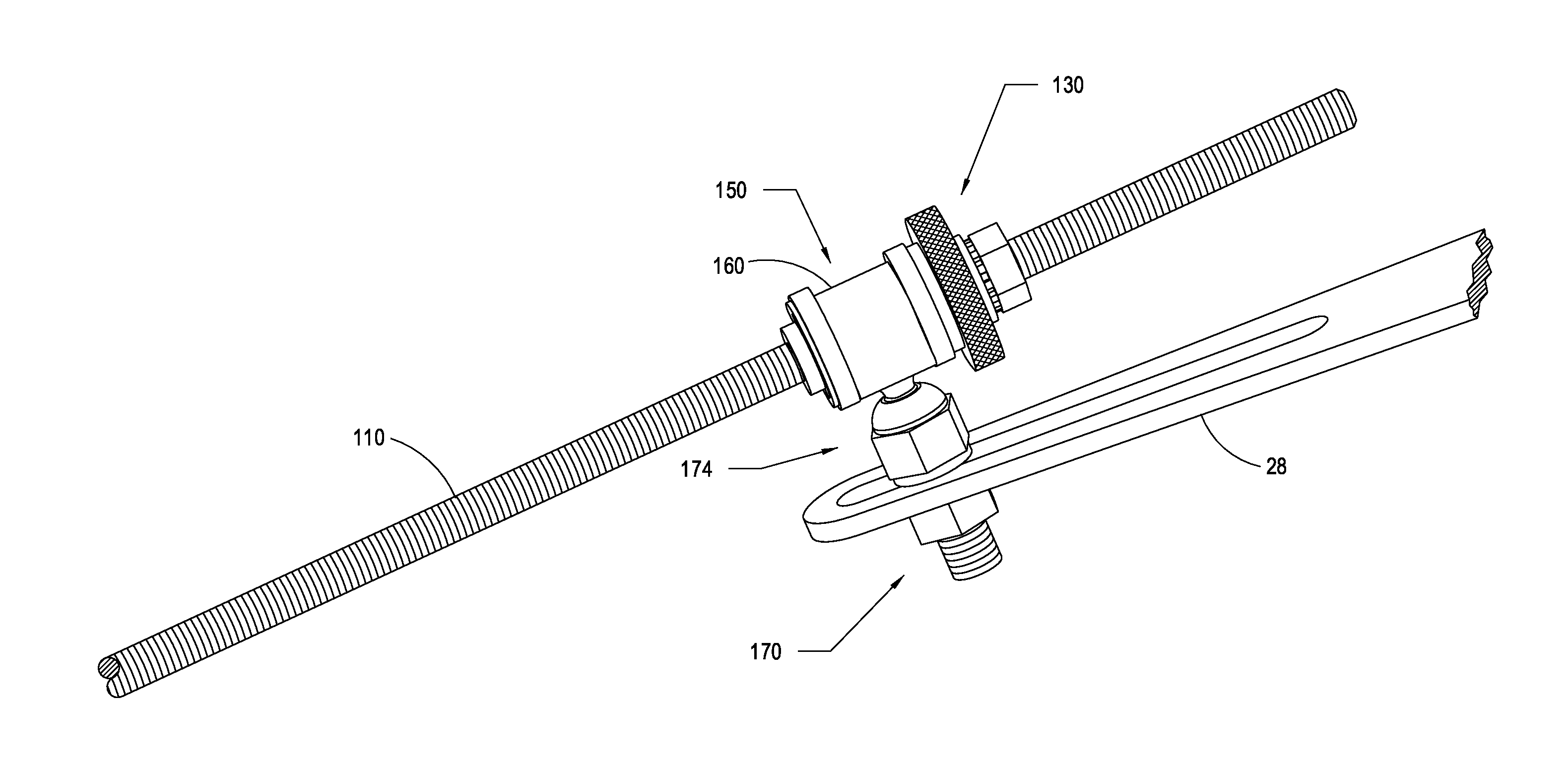
[0026]It is to be appreciated that coupling apparatuses in accordance with embodiments of the present invention reduce conventional wear, leading to a reduction in labor, operational, and maintenance costs. In addition, the ability to make very fine adjustments to the position of the coupling apparatus along the linkage rod enable more precise air / fuel ratio changes, improving the efficiency and extending the usable service life of the boiler. Furthermore, in contrast to conventional linkages, those in accordance with embodiments of the present invention permit changes to the air / fuel ratio to be made without turning off and on the equipment. Thus, fuel savings and a reduction in air contaminants may be realized.

Problems solved by technology

Nonetheless, with conventional linkage assemblies, adjustments to the linkage while the burner is in operation is not recommended because of increased risk of explosion.
These and other inherent problems with conventional coupling apparatus require the linkage rod and / or the coupling apparatus to be replaced from time to time, increasing the down time of burner operations and increasing maintenance costs.

Method used


Image

  • Linkage coupling apparatus
  • Linkage coupling apparatus
  • Linkage coupling apparatus

Examples


Embodiment Construction

[0050]The invention, in its various aspects, will be explained in greater detail below. While the invention will be described in conjunction with several exemplary embodiments, the exemplary embodiments themselves do not limit the scope of the invention. Similarly, the exemplary embodiments as illustrated in the accompanying drawings do not limit the scope of the exemplary embodiments and / or invention. Rather the invention, as defined by the claims, may cover alternatives, modifications, and / or equivalents of the exemplary embodiments.

[0051]It is to be appreciated that although the invention is described in conjunction with boiler draft burner assemblies, several embodiments of the present invention also contemplate other applications. For example, and without limitation, some aspects of the invention may be practiced to finely adjust the positioning of a device along a linkage rod. In some examples, the invention may be practiced to link a plurality of air dampers of a fan or air h...


PUM


Abstract

An apparatus for adjustably coupling a threaded linkage rod to an arm of a fuel valve, air valve, air damper, damper blade assembly, or actuator that can include a sleeve, a collar, and a lock restraining axial movement of the collar with respect to the sleeve. The sleeve may include an inside threaded wall defining a sleeve bore axially receiving the linkage rod. The collar may include (i) a collar body having a collar bore axially receiving the sleeve and (ii) an about radial extension for engagement with the arm of the fuel valve, air damper, or actuator. Rotation of the sleeve causes axial movement of the sleeve, and thus the collar locked thereto, along the linkage rod. Fine position adjustments can be made to the position of the radial extension, and thus the arm of the fuel valve, air damper, or actuator engaged thereto, with respect to the linkage rod.

Description

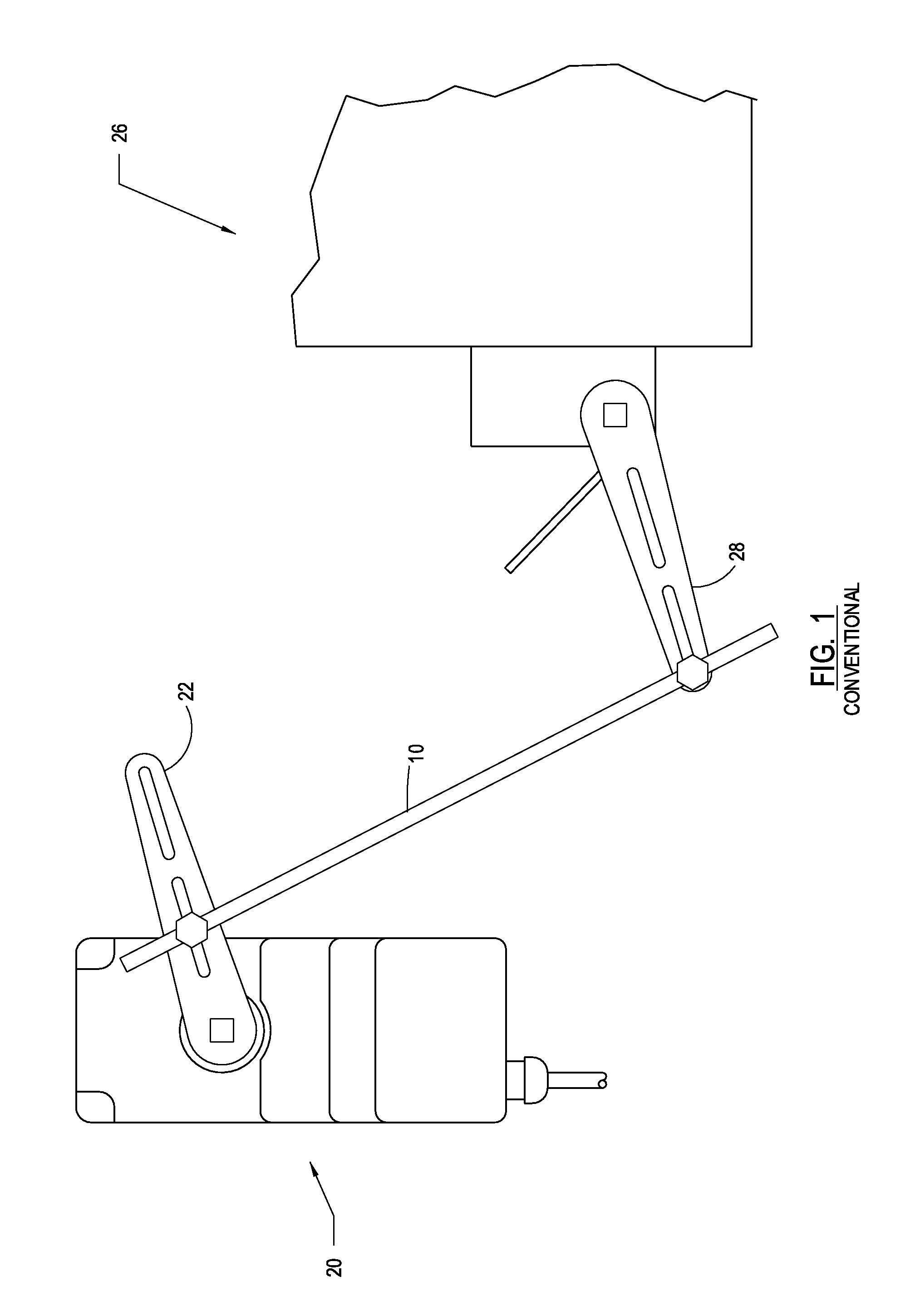
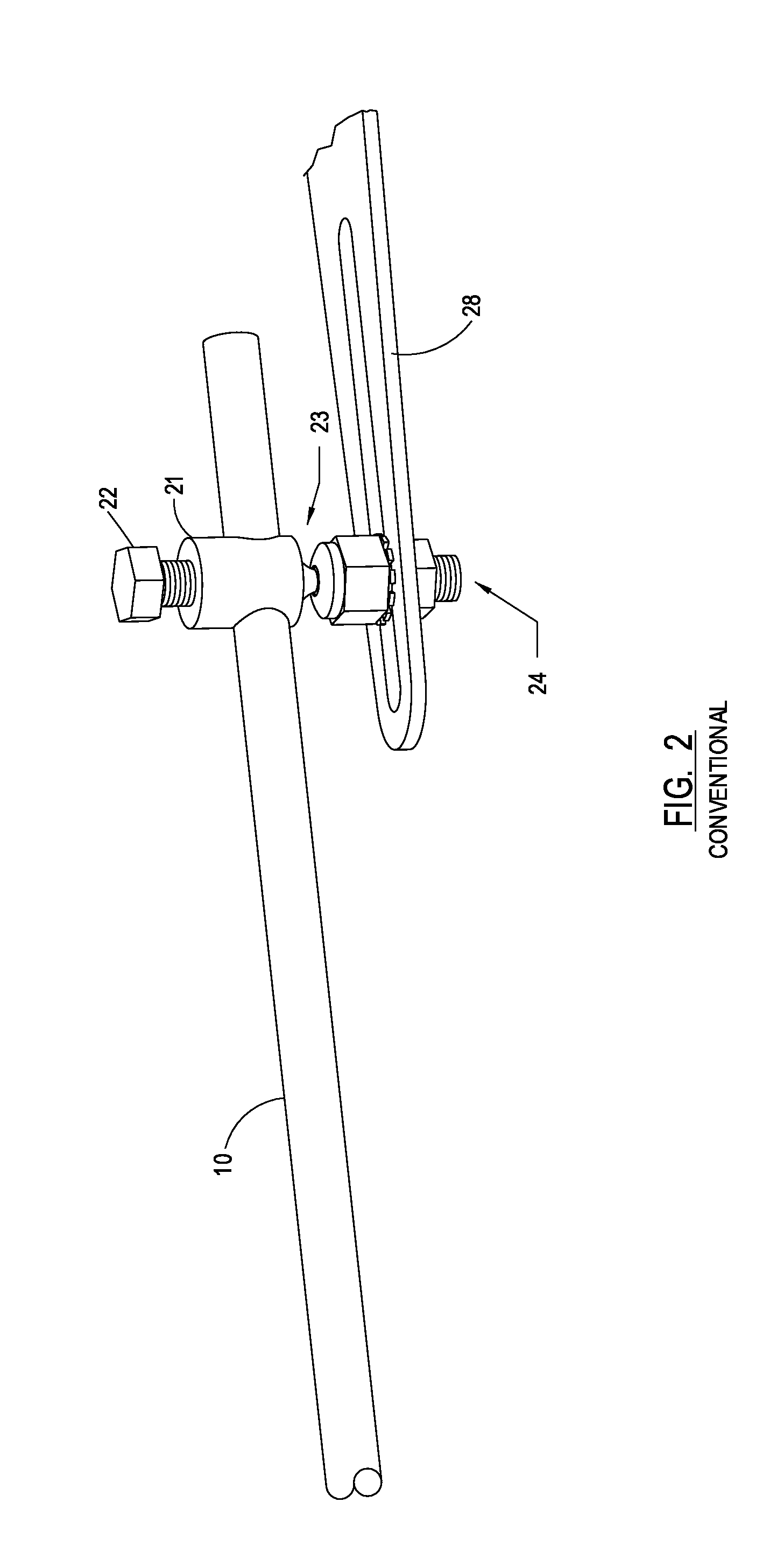
BACKGROUND OF THE INVENTION[0001]1. Field of the Invention[0002]The present invention generally relates to the field of assemblies for linking, or coupling, one or more devices. More specifically, embodiments of the present invention pertain to apparatuses for coupling fuel valves, air valves, damper assemblies, actuator motors, and / or the like in burner jackshaft assemblies.[0003]2. Background and Description of Related Art[0004]Conventional burner assemblies include linkage rods coupling a fuel valve and an air intake or inlet damper to maintain a nearly constant fuel / air ratio. Referring to the illustration of FIG. 1, a conventional burner assembly can include an air intake 26 and an actuator motor 20. In some implementations, actuator motor 20 can cooperate directly with the fuel valve. In other implementations, actuator motor 20 can be linked directly to the fuel valve much in the same way that actuator motor 20 is linked to air intake 26. In yet other implementations, a combin...

Claims


Application Information

Patent Timeline
IPC IPC(8): F16C11/00
CPCF16C11/04F16C11/045F16C11/0619Y10T403/32631Y10T74/18688Y10T403/32598Y10T403/32073Y10T403/32196
Inventor MCCLELLAND, KENNETH RAE
Owner MCCLELLAND KENNETH RAE
Learn More