
Methods and Systems for Water Delivery in an Additive Dispenser

a technology of additive dispensers and dispensers, applied in the direction of machines/engines, liquid transfer devices, bends, etc., can solve the problems of additive buildup, residue, and insufficient mixing of additives with the inflow of water, so as to prevent additive buildup or residue, improve the siphoning effect, and efficient and tidy

Active Publication Date: 2009-06-25
ELECTROLUX HOME PROD CORP NV
View PDF31 Cites 32 Cited by
  • Summary
  • Abstract
  • Description
  • Claims
  • Application Information

AI Technical Summary

Benefits of technology

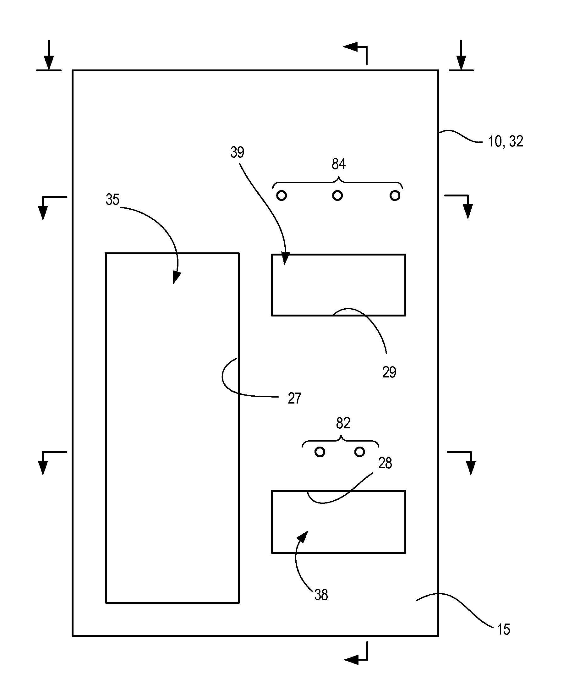
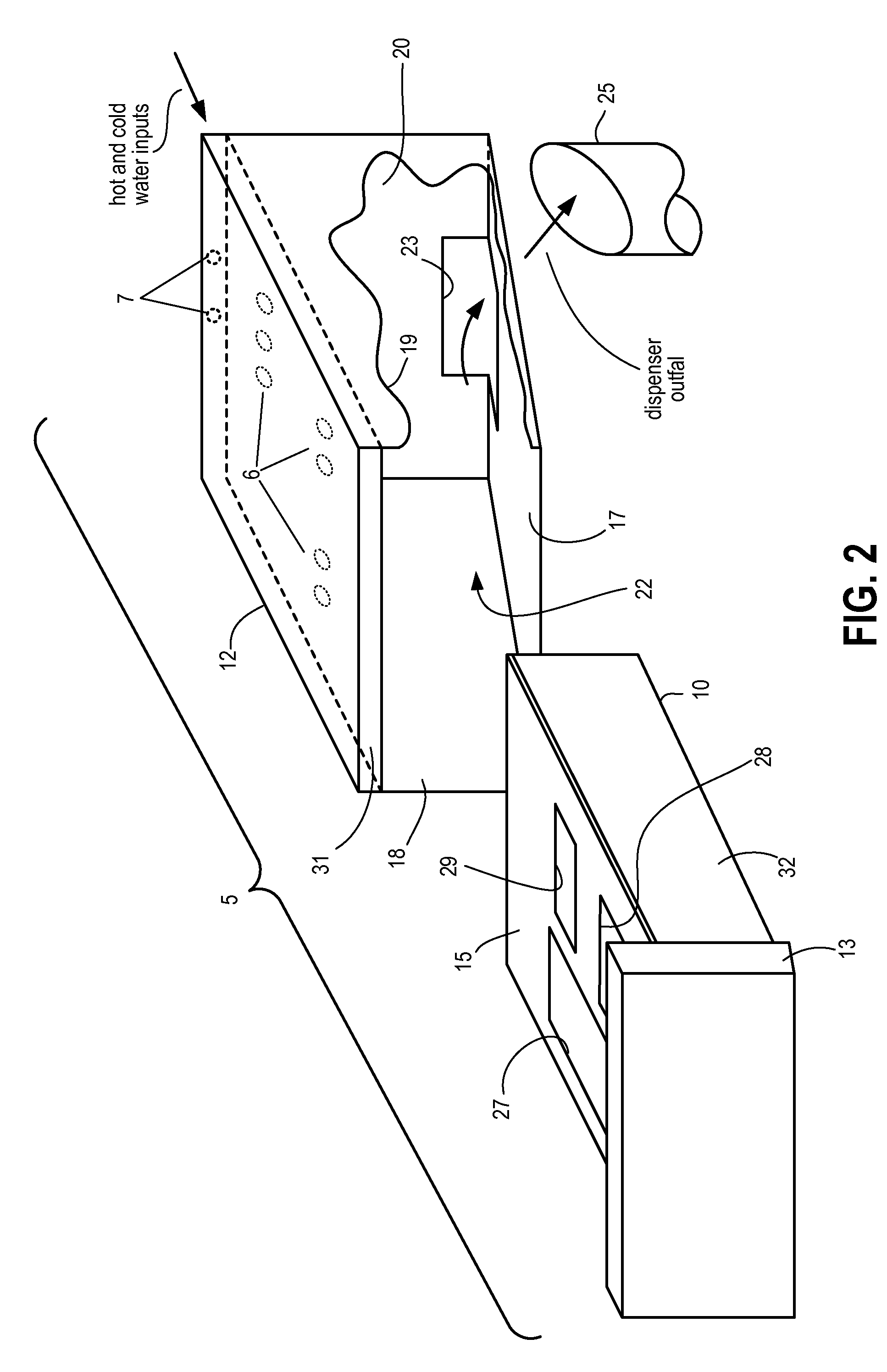
[0002]Aspects of the invention provide a system and method for diluting additives in an efficient and tidy manner. In addition to delivering water for diluting additives through a top region of an additive drawer or compartment cover, one or more water inflow tubes are used to inject water into a region of additives residing below the surface. The water inflow tubes may be attached to or integrally formed with the additive drawer or compartment cover. Water delivered from above the cover is, in part, collected in and delivered through the water inflow tubes while water is also delivered through one or more openings in the cover to the surface of an additive in the drawer or compartment. The dual injection of water provides a more even dilution of the additives in the drawer and prevents additive buildup or residue remaining in a drawer or compartment once a wash cycle is completed. Water inflow tubes may be positioned within a predefined proximity of siphon posts and siphon caps to improve the siphoning effect and to prevent unwanted residue buildup in the vicinity of the base of the siphon post and cap.

Problems solved by technology

In some instances, additives may not sufficiently mix with the inflow of water since the inflow of water is generally only from above.
In particular, additives in a bottom layer of a compartment or drawer might not be sufficiently diluted causing residue (e.g., additive buildup) to be left in the drawer or compartment at the end of a wash cycle.

Method used


Image

  • Methods and Systems for Water Delivery in an Additive Dispenser
  • Methods and Systems for Water Delivery in an Additive Dispenser
  • Methods and Systems for Water Delivery in an Additive Dispenser

Examples


Embodiment Construction

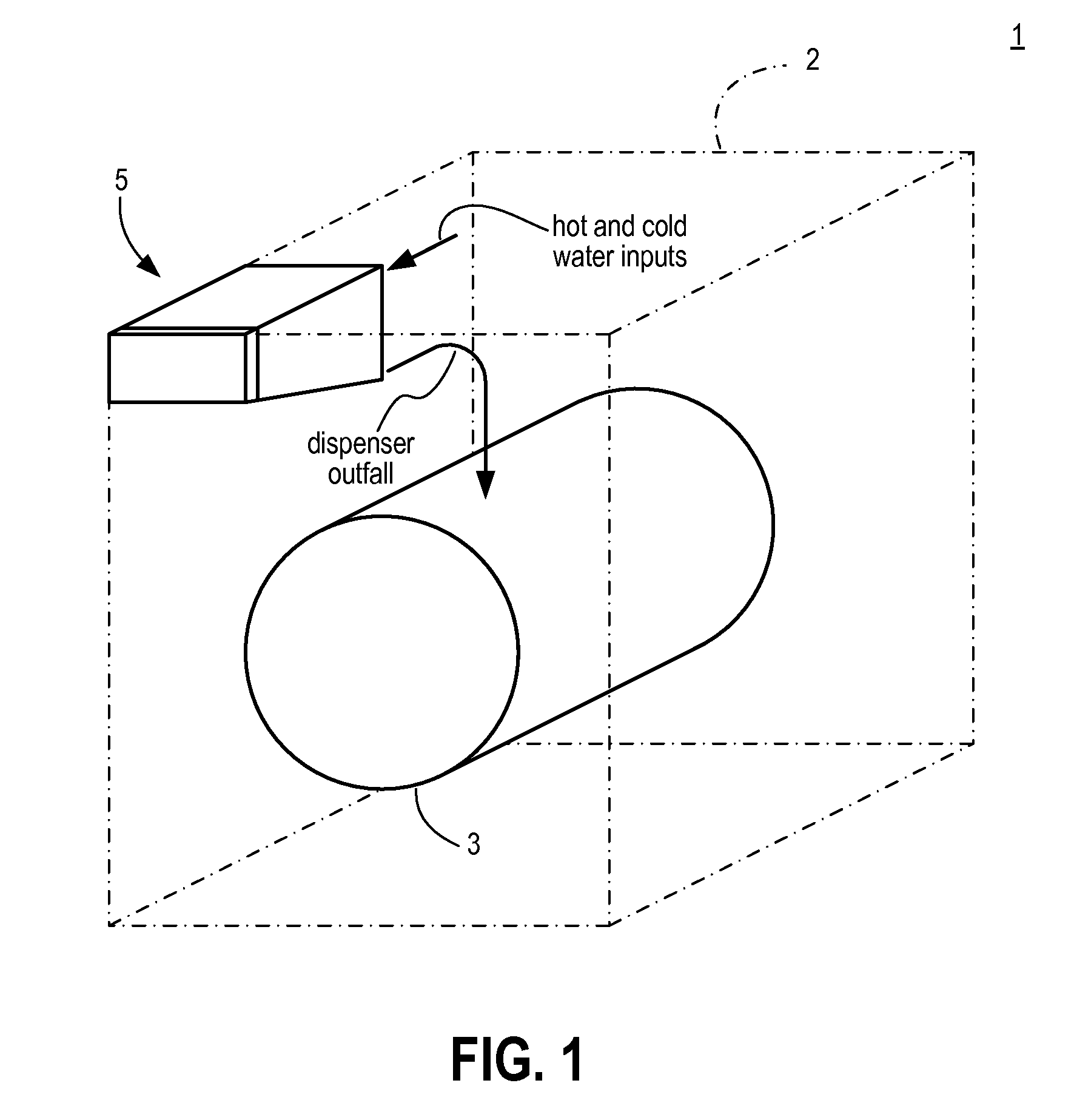
[0020]Although various embodiments are described herein using a front-loading clothes washing (or laundry) machine as an example, the invention is not limited to front loading washers. In other embodiments, additive dispensers similar to those described herein are incorporated into top loading washing machines. The invention is not limited to laundry equipment. Additive dispensers similar to those described herein can also be used in automated dishwashing equipment, as well as in other devices. Indeed, dispensers such as those described herein can be used in devices that perform no washing function.

[0021]FIG. 1 is a partially schematic front perspective view of a clothes washing machine 1 according to at least some embodiments. The housing 2 of washing machine 1 is shown with uneven broken lines, and numerous details of washing machine 1 have been omitted so as not to obscure this description with unnecessary details. As seen in FIG. 1, washing machine 1 is of the front-loading type...


PUM


Abstract

A washing apparatus such as an automatic laundry washing machine includes a wash agent dispenser drawer including an additive compartment for storing various additives such as detergent, bleach and fabric softener. One or more water inflow tubes may extend downwardly into the additive compartment and may be configured to deliver water for diluting the additives contained in the compartment. The inflow tubes are of sufficient length to reach a sub-surface portion of additive held in the compartment. Water may simultaneously be delivered to the surface of the additive. Furthermore, inflow tubes have their outlets positioned adjacent to the base(s) of one or more siphon post / cap assemblies located in the additive compartments, such that a churning effect is produced from the injection of water through the tubes and the siphoning action of the siphon post, whereby mixing is enhanced and additive buildup may be avoided and / or removed.

Description

BACKGROUND[0001]Automated washing machines (such as laundry washing machines) often include mechanisms for dispensing additives into a washing chamber (e.g., a drum of a laundry washing machine). Some dispensers contain receptacles or chambers for different additives, which can include detergents, whiteners, fabric softeners, scents, rinse aids, etc. Typically, a user fills a dispenser chamber with one or more additives. During a wash cycle, water is then automatically introduced into the dispenser chamber and mixes with the additive. The water / additive mixture then flows into a separate washing chamber. In some instances, additives may not sufficiently mix with the inflow of water since the inflow of water is generally only from above. In particular, additives in a bottom layer of a compartment or drawer might not be sufficiently diluted causing residue (e.g., additive buildup) to be left in the drawer or compartment at the end of a wash cycle.BRIEF SUMMARY OF SELECTED INVENTIVE AS...

Claims


Application Information

Patent Timeline
IPC IPC(8): D06F39/02B65G51/00F04F10/00B65D1/24F16L43/00
CPCD06F39/02Y10T137/2713
Inventor HILL, CHRIS H.
Owner ELECTROLUX HOME PROD CORP NV
Learn More