
Variable engine out emission control roadmap

a technology of emission control and variable engine, applied in the direction of electrical control, exhaust treatment electric control, instruments, etc., can solve the problems of increasing the cost of calibration, affecting the efficiency of the calibration process, and affecting the approach. , to achieve the effect of reducing the calibration effor

Inactive Publication Date: 2009-06-25
DETROIT DIESEL CORP
View PDF17 Cites 55 Cited by
  • Summary
  • Abstract
  • Description
  • Claims
  • Application Information

AI Technical Summary

Benefits of technology

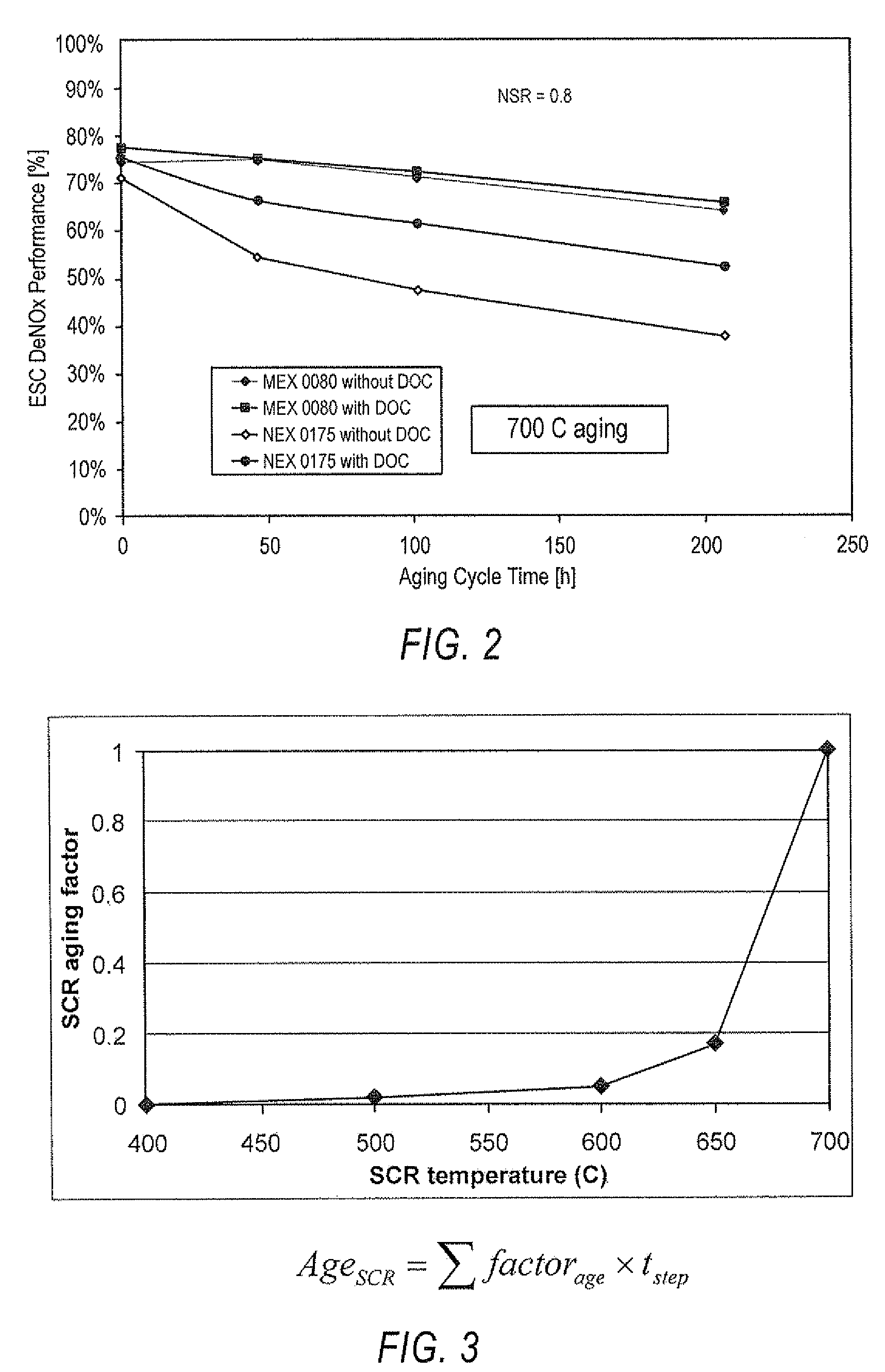
[0003]In one aspect, the present invention is related to a method to operate an internal combustion engine equipped with an electronic control system (ECS) having memory, and an exhaust system including a diesel particulate filter (DPF) and a Selective Catalytic Reducer (SCR) for NOx emission reduction over all ages of said SCR. The steps comprise determining the age of the SCR with an age factor; determining SCR efficiency using SCR age as a factor of SCR efficiency; determining desired tailpipe NOx emissions as setpoints to control engine out NOx emissions; determining desired engine out NOx emission by using current SCR efficiency and desired tailpipe NOx emissions; using fuzzy logic to manage engine control setpoints which forms a forward control portion of the said ECS; and using closed loop engine out NOx sensor feedback control to accurately control engine out NOx emissions.
[0004]The engine control setpoints include beginning of injection (BOI) exhaust gas recirculation valve (EGR), and NOP, and the NOx setpoints are determined from a 3D table in memory with engine load and engine rpm as inputs. The engine out NOx is controlled according to SCR deterioration age includes determining the efficiency of the SCR and the amount of NOx engine out emission produced in a predetermined time period, reducing engine fuel consumption based upon said SCR efficiency and NOx engine out and maximize DPF regeneration, extending the DPF active regeneration interval.

Problems solved by technology

A shortcoming to this approach has been that as the SCR ages, it efficiency decreases and the SCR is further affected by high temperature gasses in the exhaust stream.
However, this approach is not always satisfactory, especially when the SCR is new, as the engine calibration must accommodate the increased efficiency of a new system as opposed to an older system or a system that is aging.
In addition, operating an engine as if the SCR is already aged will unduly age the SCR by subjecting it to higher temperature exhaust gasses than is necessary for a new SCR to be effective.
Fuel efficiency is also adversely impacted when calibrating the engine to operate in a manner that assumes an aged SCR.

Method used


Image

  • Variable engine out emission control roadmap
  • Variable engine out emission control roadmap
  • Variable engine out emission control roadmap

Examples


Embodiment Construction

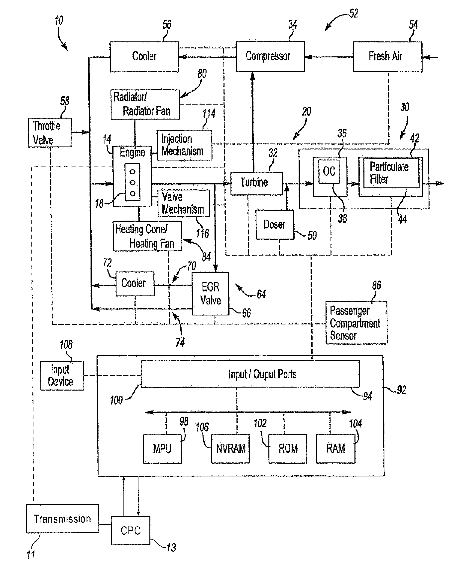
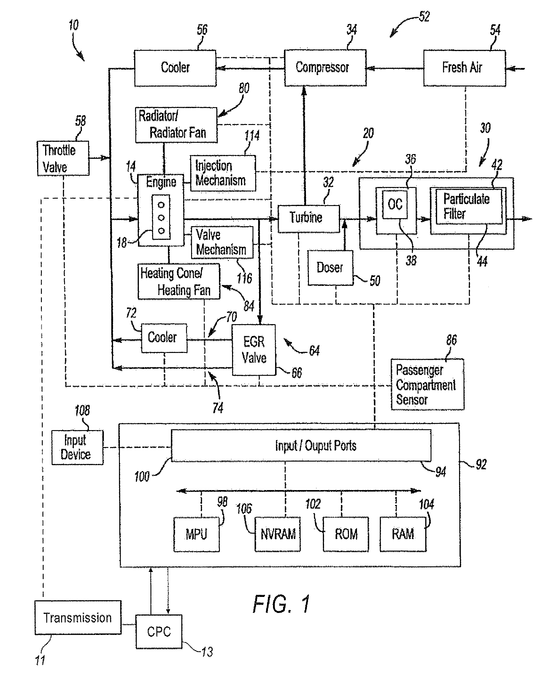
[0024]FIG. 1 illustrates a vehicle powertrain system 10 in accordance with one non-limiting aspect of the present invention. The system 10 may provide power for driving any number of vehicles, including on-highway trucks, construction equipment, marine vessels, stationary generators, automobiles, trucks, tractor-trailers, boats, recreational vehicle, light and heavy-duty work vehicles, and the like.

[0025]The system 10 may be referred to as an internal combustion driven system wherein fuels, such as gasoline and diesel fuels, are burned in a combustion process to provide power, such as with a spark or compression ignition engine 14. The engine 14 may be a diesel engine that includes a number of cylinders 18 into which fuel and air are injected for ignition as one skilled in the art will appreciate. The engine 14 may be a multi-cylinder compression ignition internal combustion engine, such as a 4, 6, 8, 12, 16, or 24 cylinder diesel engines, for example. It should be noted, however, t...


PUM


Abstract

A method for operating an internal combustion engine for variable engine out NOx control talking into account the age of the SCR.

Description

TECHNICAL FIELD[0001]Heavy duty diesel engines have been the subject of much legislation to reduce emission levels, One way to reduce emissions, especially NOx emissions, is by adapting engine operation to include Selective Catalytic Reducers (SCR) in the exhaust systems to reduce the amount of NOx emitted to the atmosphere. A shortcoming to this approach has been that as the SCR ages, it efficiency decreases and the SCR is further affected by high temperature gasses in the exhaust stream. Normal engine operation is to calibrate engine out NOx emissions to a level so that the tail pipe NOx meets legislated requirements with an aged SCR. However, this approach is not always satisfactory, especially when the SCR is new, as the engine calibration must accommodate the increased efficiency of a new system as opposed to an older system or a system that is aging. In addition, operating an engine as if the SCR is already aged will unduly age the SCR by subjecting it to higher temperature ex...

Claims


Application Information

Patent Timeline
Patent Type & Authority Applications(United States)
IPC IPC(8): F01N9/00G06F19/00G01M15/04
CPCF01N3/0231Y02T10/47F01N9/00F02B29/0406F02D13/04F02D41/005F02D41/0235F02D41/1404F02D41/146F02D41/401F02D2041/1432F02D2200/0802F02M25/0707F02M25/0728Y02T10/44F01N3/18F02M26/05F02M26/25Y02T10/40
Inventor SUN, MIN
Owner DETROIT DIESEL CORP
Learn More