Backlight inverter and method of driving same

a backlight inverter and inverter technology, applied in the field of backlight inverters, can solve the problems of parasitic capacitance fluctuation at the lamp, transformer not necessarily achieving good power efficiency, and difficulty in designing a transformer, so as to reduce the influence of parasitic capacitance on lamp current, eliminate flickering on the lcd screen, and improve uniformity

Inactive Publication Date: 2009-06-18
MINEBEA CO LTD
View PDF4 Cites 12 Cited by
  • Summary
  • Abstract
  • Description
  • Claims
  • Application Information

AI Technical Summary

Benefits of technology

[0019]The present invention has been made in light of the above problem and accomplished based on measurement data indicating that an inverter transformer should be driven at an operating frequency which is included in a frequency range between a parallel resonance frequency and a series resonance frequency of a resonance circuit formed at the secondary side of an inverter transformer and also which is not included in a frequency range corresponding to a peak waveform appearing within the above frequency range in the gain characteristic curve of the inverter transformer, and an object of the present invention is to provide a backlight inverter for lighting a plurality of lamps, wherein a stable lamp current flows through a CCFL without receiving influences of lamp temperature thereby stabilizing the brightness of an LCD screen from the start of lighting the CCFL, and is also to provide a method of driving such a backlight inverter.
[0032]With the backlight inverter and the driving method thereof according to the present invention, a stable current flows through a plurality of cold cathode fluorescent lamps without receiving influence of lamp temperature, and as a result, the brightness of an LCD screen is stabilized even immediately after cold starting.
[0033]Also, with the backlight inverter and the driving method thereof according to the present invention, the influence of a parasitic capacitance on lamp current is reduced, and therefore the lamp current in the plurality of cold cathode fluorescent lamps can be better uniformed. Consequently, the flickering on the LCD screen is eliminated.
[0034]Further, with the backlight inverter and the driving method thereof according to the present invention, the conversion efficiency ratio of the backlight inverter is enhanced, and therefore the heat generation in the inverter transformer and switching elements to drive the inverter transformer can be reduced. As a result, for example, in a backlight inverter including a plurality of FET bridges with no heat sink, the number of bridges is reduced and so components for a gate driving circuit, a decoupling capacitor, and the like can be reduced. On the other hand, in a backlight inverter including a plurality of FET bridges with a heat sink, the heat sink can be downsized or may even be eliminated, which enables the backlight inverter to be downsized and also to be produced inexpensively.

Problems solved by technology

When the transformer is driven at the resonance frequency as described above, however, a phase difference is caused between voltage and current at the primary side of the transformer, and the transformer does not necessarily achieve good power efficiency.
Also, a resonance frequency of a high order is present at the secondary side of the transformer, and therefore it can happen that the transformer operates at such a resonance frequency of a high order or that the transformer is likely to be influenced by the resonance frequency during operation, which poses a difficulty in designing a transformer.
Further, a large fluctuation in lamp impedance means fluctuation also in lamp voltage, and consequently the parasitic capacitance formed at the lamp is caused to fluctuate, too.
However, since the driving method described above is used for lighting one to several CCFLs, it is difficult for one backlight inverter to stably light more CCFLs, for example, typically eight to sixteen CCFLs, in a controlled manner, and the lamp voltages of the individual CCFLs fluctuate thereby causing fluctuation of the currents flowing in the parasitic capacitance of the CCFLs, which makes the brightness unstable thus flickering the screen of the LCD.
The fact that lamp impedance fluctuates largely means that lamp voltage also fluctuates, and consequently current flowing in the parasitic capacitance of the lamp is caused to fluctuate.
However, in the driving method described in Patent Document 3, it may possibly happen that in the case of driving a backlight inverter in which such an abrupt variation region as described above occurs in the gain characteristics curve, a frequency included in the frequency range corresponding to the abrupt variation region is set as a driving frequency, in which case fluctuation in lamp current becomes large and therefore the brightness of CCFL becomes unstable thus causing the LCD screen to flicker.
Also, at low environmental temperatures, since the variation region has a greater sharpness compared with at ordinary temperatures, the fluctuation is notably larger thereby causing a large irregularity in the brightness distribution.

Method used


Image

  • Backlight inverter and method of driving same
  • Backlight inverter and method of driving same
  • Backlight inverter and method of driving same

Examples


Embodiment Construction

[0046]Exemplary embodiments of the present invention will hereinafter be described with reference to the accompanying drawings.

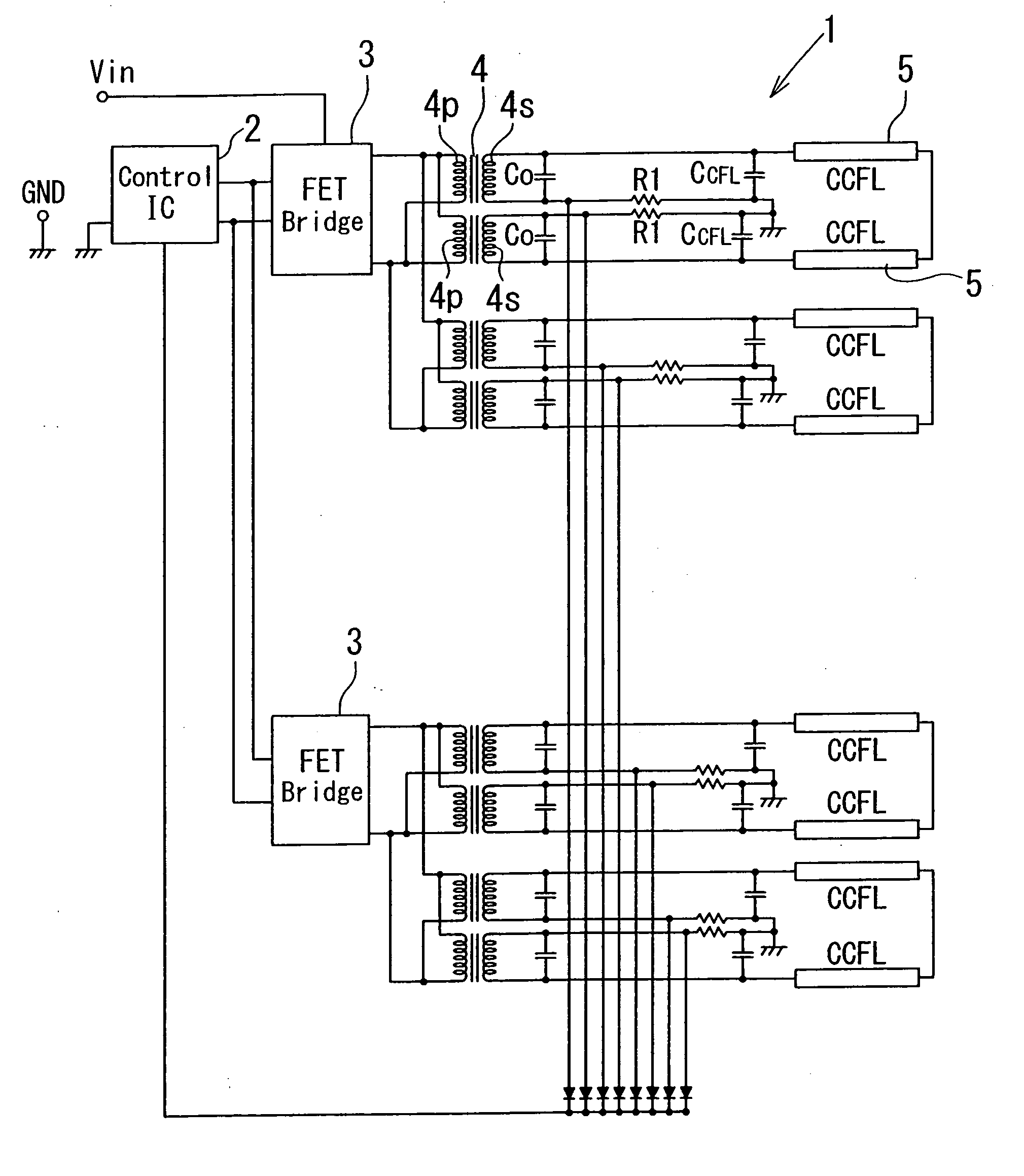
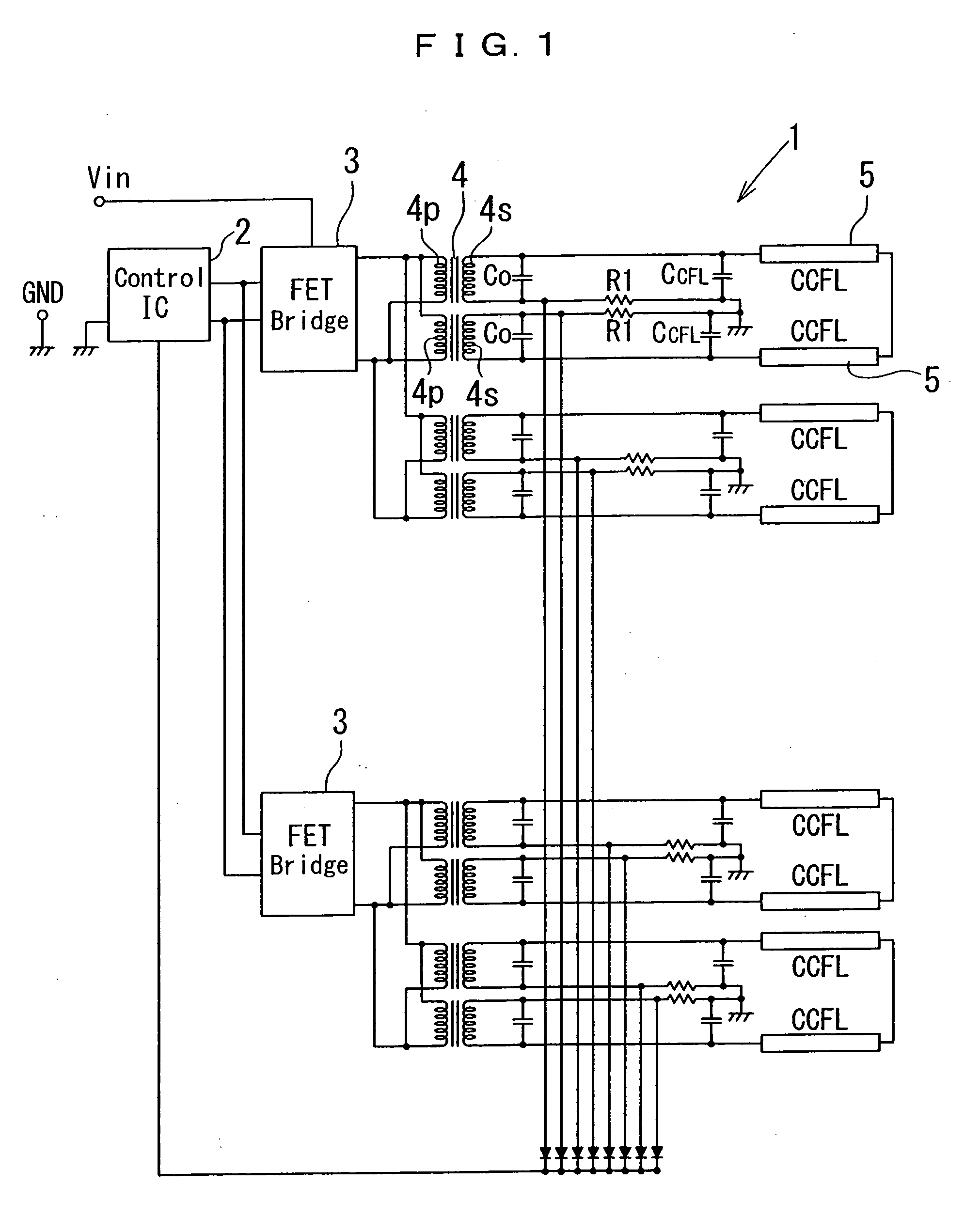
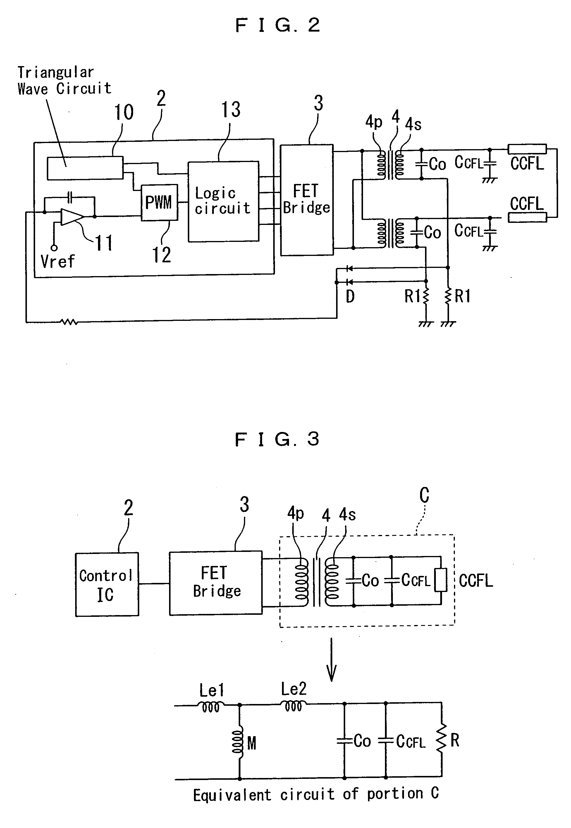
[0047]FIG. 1 shows a circuitry of a relevant portion of a backlight inverter 1 according to an embodiment of the present invention. The backlight inverter 1 shown in FIG. 1 is suitable as a backlight for use in, for example, a large LCD TV, and includes a plurality (two in the figure) of FET bridges 3, a plurality (four in the figure) of inverter transformers 4, a plurality (eight in the figure) of CCFLs 5 and one control IC 2, wherein the plurality of FET bridges 3 are activated by the one control IC 2 thereby driving the plurality of CCFLs 5.

[0048]The FET bridges 3 are each constituted by, for example, an H-bridge (full-bridge) which is structured such that two series circuits each including a p-MOSFET and an n-MOSFET and are connected in parallel to each other and which drives a load, and are connected to the primary sides of the inverter transformers 4.

[...


PUM


Abstract

A backlight inverter is provided which includes at least one inverter transformer and to which a plurality of cold cathode fluorescent lamps are connected, wherein a plurality of primary windings of the inverter transformer are connected to each other either in series or in parallel, a resonance circuit including a leakage inductance and a capacitance component is formed at the secondary side of the inverter transformer, and wherein the inverter transformer is driven at an operating frequency which is included in a frequency range between a parallel resonance frequency and a series resonance frequency of the resonance circuit and which excludes a frequency range between a first inflection point and a second inflection point of a gain characteristic curve of the inverter transformer.

Description

BACKGROUND OF THE INVENTION[0001]1. Field of the Invention[0002]The present invention relates to a backlight inverter for driving a light source to illuminate a liquid crystal display screen, particularly a backlight inverter for driving a plurality of lamps for a large liquid crystal display television (LCD TV), and also relates to a method of driving such a backlight inverter.[0003]2. Description of the Related Art[0004]While recently a liquid crystal display (LCD) is widely used for use as a display device for a personal computer and the like, a lighting means, such as a backlight, is required for illuminating the screen of the LCD. In order to light the screen of the LCD brightly, a plurality of cold cathode fluorescent lamps (hereinafter referred to as “CCFLs”) are used as a light source, and are simultaneously discharged and lit.[0005]Generally, for discharging and lighting a CCFL for a backlight, an inverter circuit which includes an inverter unit incorporating a full-bridge ...

Claims


Application Information

Patent Timeline
IPC IPC(8): H02M1/00
CPCH05B41/2828
Inventor TAKATSUKA, SHINGOSUZUKI, MITSUAKI
Owner MINEBEA CO LTD
Why Eureka
Try Eureka