
Electrically-driven liquid crystal lens and stereoscopic display device using the same

a liquid crystal lens and stereoscopic display technology, applied in the direction of optics, instruments, electrical equipment, etc., can solve the problems of deteriorating image quality, deteriorating transmissivity, and visual sensitivity deterioration

Active Publication Date: 2009-06-18
LG DISPLAY CO LTD
View PDF6 Cites 55 Cited by
  • Summary
  • Abstract
  • Description
  • Claims
  • Application Information

AI Technical Summary

Benefits of technology

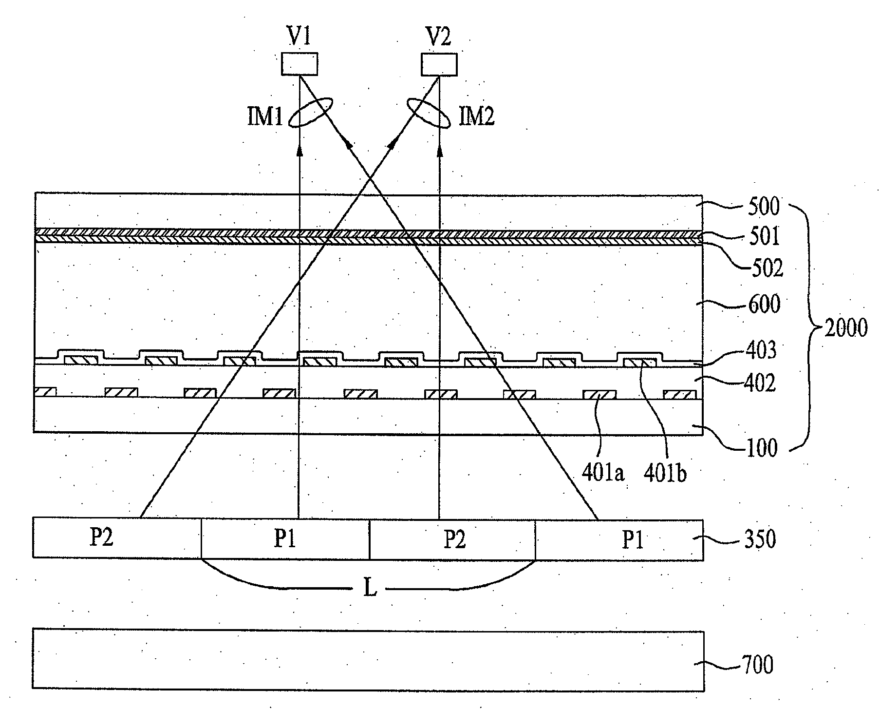
[0020]An electrically-driven liquid crystal lens comprises: first and second substrates arranged opposite each other and each including a plurality of lens regions; a plurality of first electrodes formed on the first substrate to correspond to the respective lens regions while being spaced apart from one another, to which voltages gradually increasing from the center to the edge of each lens region are applied; a second electrode formed over the entire surface of the second substrate; a first alignment film formed over the entire surface of the first substrate including the first electrodes and having an alignment direction parallel to or perpendicular to a longitudinal direction of the first electrodes; a second alignment film formed on the second electrode and having an anti-parallel alignment direction relative to the first alignment film; and a liquid crystal layer filled between the first substrate and the second substrate.

Problems solved by technology

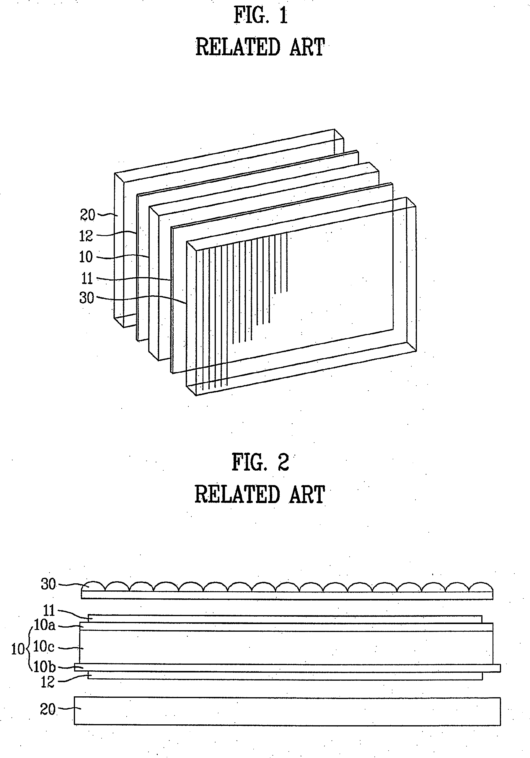
This bending phenomenon results in abnormal optical pathways through the backlight unit 20, liquid crystal panel 10 and lenticular plate 30, thereby deteriorating image quality.
Moreover, the adhesive problematically causes deterioration in transmissivity.
With relation to attachment of the above-described lenticular lens, there are problems, such as the use of an adhesive, deterioration in visual sensitivity due to the bending phenomenon causes, or a difficulty in the processing of a smooth lenticular lens.

Method used


Image

  • Electrically-driven liquid crystal lens and stereoscopic display device using the same
  • Electrically-driven liquid crystal lens and stereoscopic display device using the same
  • Electrically-driven liquid crystal lens and stereoscopic display device using the same

Examples


first embodiment

[0093]FIG. 7A is a sectional view illustrating an electrically-driven liquid crystal lens and FIGS. 7B and 7C are views illustrating alignment shape of liquid crystals on a per distance basis in one lens region before and after application of voltages in the configuration of FIG. 7A.

[0094]As shown in FIG. 7A, in the electrically-driven liquid crystal lens according to a first embodiment of the present invention, the first and second alignment films 403 and 502 are aligned in the longitudinal direction of the first electrodes 401a and 401b on the first substrate 400 (in a direction into the drawing). In this case, the liquid crystals of the liquid crystal layer 600 have positive dielectric constant anisotropy. Each of the first and second alignment films 403 and 502 is a horizontal alignment film having a tilt angle of less than 1°, and the alignment direction thereof is defined via rubbing. The first and second alignment films 403 and 502 are subjected to rubbing in an anti-paralle...

second embodiment

[0097]FIG. 8A is a sectional view illustrating an electrically-driven liquid crystal lens and FIGS. 8B and 8C are views illustrating alignment shape of liquid crystals on a per distance basis in one lens region before and after application of voltages in the configuration of FIG. 8A.

[0098]As shown in FIG. 8A, in the electrically-driven liquid crystal lens according to a second embodiment of the present invention, the first and second alignment films 403 and 502 are aligned perpendicular to the longitudinal direction of the first electrodes 401a and 401b on the first substrate 400 (in a horizontal direction in the drawing). In this case, the liquid crystals of the liquid crystal layer 600 have positive dielectric constant anisotropy. Each of the first and second alignment films 403 and 502 is a horizontal alignment film having a tilt angle of less than 1°, and the alignment direction thereof is defined via rubbing. The first and second alignment films 403 and 502 are subjected to ru...

third embodiment

[0101]FIG. 9A is a sectional view illustrating an electrically-driven liquid crystal lens and FIGS. 9B and 9C are views illustrating alignment shape of liquid crystals on a per distance basis in one lens region before and after application of voltages in the configuration of FIG. 9A.

[0102]As shown in FIG. 9A, in the electrically-driven liquid crystal lens according to a third embodiment of the present invention, the first and second alignment films 403 and 502 are aligned in the longitudinal direction of the first electrodes 401a and 401b on the first substrate 400 (in a direction into the drawing). In this case, the liquid crystals of the liquid crystal layer 600 have negative dielectric constant anisotropy. Each of the first and second alignment films 403 and 502 is a vertical alignment film having a tilt angle of more than about 89°, and the alignment direction thereof is defined by rubbing. The first and second alignment films 403 and 502 are subjected to rubbing in an anti-par...


PUM

PropertyMeasurementUnit
tilt angleaaaaaaaaaa
voltagesaaaaaaaaaa

Abstract

An electrically-driven liquid crystal lens wherein an electrode is defined with a vertical or horizontal rubbing direction, achieving an improved lens profile effect, and a stereoscopic display device using the same are disclosed. The liquid crystal lens includes first and second substrates arranged opposite each other and each including a plurality of lens regions, a plurality of first electrodes formed on the first substrate to correspond to the respective lens regions while being spaced apart from one another, to which voltages gradually increasing from the center to the edge of each lens region are applied, a second electrode formed over the entire surface of the second substrate, a first alignment film formed over the entire surface of the first substrate including the first electrodes and having an alignment direction parallel to or perpendicular to a longitudinal direction of the first electrodes, a second alignment film formed on the second electrode and having an anti-parallel alignment direction relative to the first alignment film, and a liquid crystal layer filled between the first substrate and the second substrate.

Description

[0001]This application claims the benefit of the Korean Patent Application No. P2007-133484, filed on, Dec. 18, 2007, which is hereby incorporated by reference as if fully set forth herein.BACKGROUND OF THE INVENTION[0002]1. Field of the Invention[0003]The present invention relates to an electrically-driven liquid crystal lens, and more particularly, to an electrically-driven liquid crystal lens wherein electrodes are defined with a vertical or horizontal rubbing direction, achieving improved lens-profile effects, and a stereoscopic display device using the same.[0004]2. Discussion of the Related Art[0005]At present, services for rapid dissemination of information, based on high-speed information communication networks, have developed from a simple “listening and speaking” service, such as current telephones, to a “watching and listening” multimedia type service based on digital terminals used for high-speed processing of characters, voice and images, and are expected to be ultimate...

Claims


Application Information

Patent Timeline
Patent Type & Authority Applications(United States)
IPC IPC(8): G02F1/1337H04N13/04G02F1/1335
CPCG02F1/134309G02F1/13471H04N13/0456H04N13/0454H04N13/0404H04N13/305H04N13/359H04N13/361G02F1/13
Inventor JUNG, SUNG MIN
Owner LG DISPLAY CO LTD
Learn More