
Anti-rotation mechanism for a closed piston torque converter

Inactive Publication Date: 2009-06-18
SCHAEFFLER TECH AG & CO KG
View PDF12 Cites 5 Cited by
  • Summary
  • Abstract
  • Description
  • Claims
  • Application Information

AI Technical Summary

Benefits of technology

[0012]It is a general object of the present invention to provide an anti-rotation mechanism for a closed piston, three-passage torque converter that mitigates or eliminates rattling during operation, is cost effective, and may be implemented on a stamped piston.

Problems solved by technology

These seals are designed for axially directed movement of the piston, but are not durable to rotation about the central axis of rotation.
As engine torsionals act directly on the outer mating components of these seals, but not on the piston itself, the piston inertia creates a driving force counter to that of the outer mating components, which results in rotation relative to these components.
Unfortunately, this splined arrangement is costly, difficult to implement on a stamped piston, and is prone to rattle.
Rattling is particularly an issue on large diesel engines.

Method used


Image

  • Anti-rotation mechanism for a closed piston torque converter
  • Anti-rotation mechanism for a closed piston torque converter
  • Anti-rotation mechanism for a closed piston torque converter

Examples


second embodiment

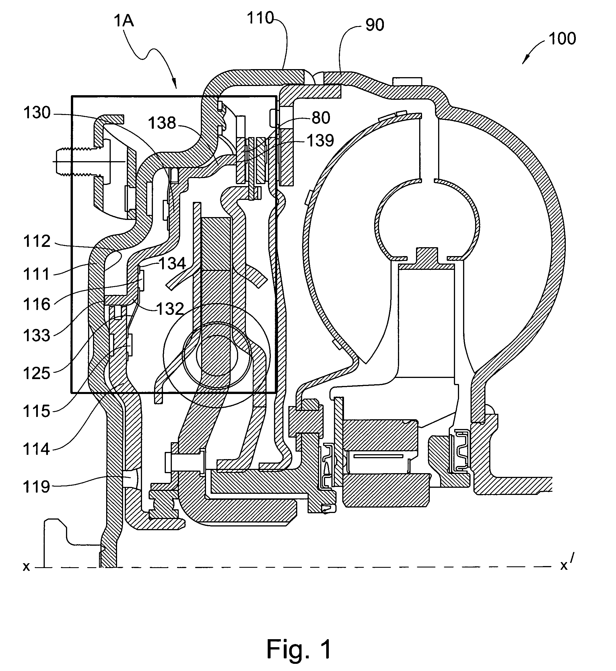
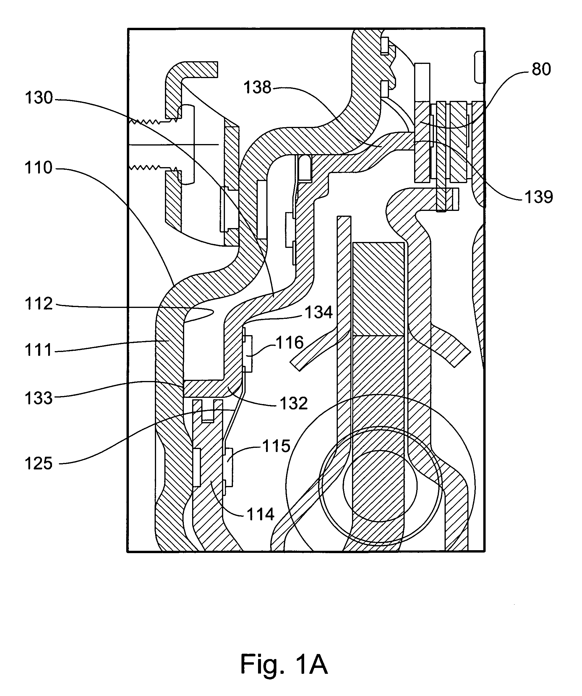
[0037]FIG. 2 is a partial cross-sectional view of present invention piston plate attachment in a torque converter 100. In this embodiment, which does not include leaf spring 125, cover 110 further comprises at least one dog 105, but preferably a plurality of dogs 105, axially extruding toward the rear from inner radial surface 112. Piston plate 130 further comprises at least one receiving element 106, but preferably a plurality of receiving elements 106, axially extending toward the front from front annular edge 133. The plurality of receiving elements 106 are operatively arranged to axially and slidingly engage the plurality of dogs 105. Once slidingly engaged, the plurality of dogs 105 prevents piston plate 130 from rotating relative to cover 110, while allowing its axial movement.

third embodiment

[0038]FIGS. 3-5A show the present invention. In this embodiment, at least one leaf spring, but preferably a plurality of leaf springs, are used to secure the piston plate to the drive plate. The drive plate is rotationally fixed to the torque converter cover, for example, with leaf springs. In an alternative embodiment, however, the leaf spring attaches directly from the piston to the cover, for example, with extruded rivets.

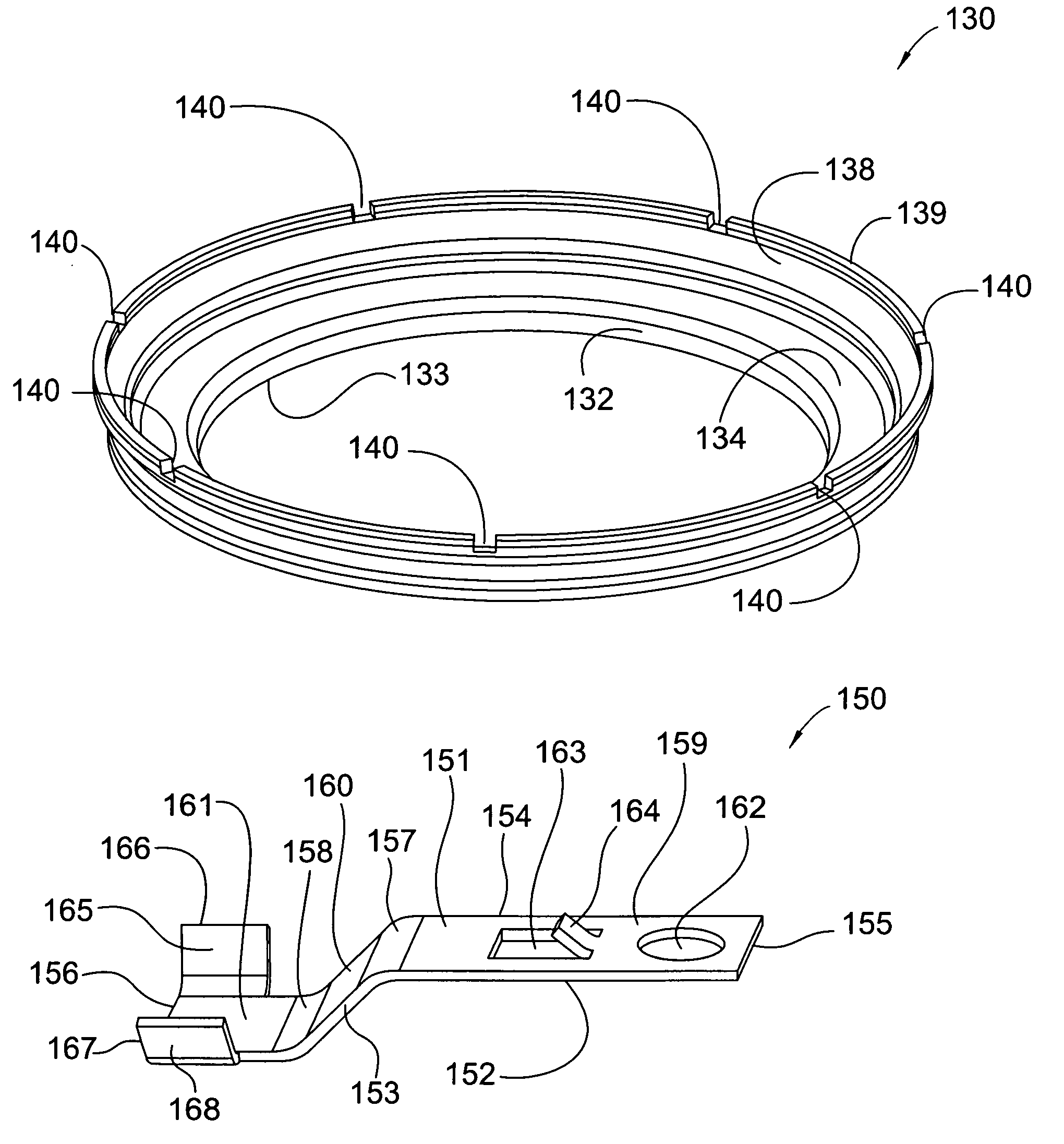
[0039]FIG. 3 shows a perspective view of piston 130, which in this embodiment further comprises at least one plate cut 140, but preferably a plurality of plate cuts 140 for receiving a plurality of leaf springs 150.

[0040]FIG. 4 shows a perspective view of leaf spring 150, which is generally flat and elongate and comprises: top surface 151 and bottom surface 152; first end 155 and second end 156; sides 153 and 154; first segment 159, second segment 160, and third segment 161; and, bend 157, arranged between first segment 159 and second segment 160, and bend 158, ...

fourth embodiment

[0042]FIGS. 6-8A show the present invention. In this embodiment, at least one leaf spring, but preferably a plurality of leaf springs, is used to secure the piston plate to the drive plate. The drive plate is rotationally fixed to the torque converter cover, for example, with leaf springs. In an alternative embodiment, however, the leaf spring attaches directly from the piston to the cover, for example, with extruded rivets. FIG. 6 shows a perspective view of piston 230, which in this embodiment further comprises at least one plate cut 240, but preferably a plurality of plate cuts 240 for receiving a plurality of leaf springs 250. Plate cut 240 includes peg 242 disposed generally in the middle of plate cut 240.

[0043]FIG. 7 shows a perspective view of leaf spring 250, which is generally flat and elongate and comprises: first end 255 and second end 256; sides 253 and 254; first segment 259, second segment 260, and third segment 261; and, bend 257, arranged between first segment 259 an...


PUM


Abstract

A piston plate anti-rotate mechanism in a closed piston, three passage torque converter including a cover having an inner radial surface, a drive plate comprising an annular plate, a piston plate having an axial inner crown, a front annular edge, an axial skirt, and a back annular edge, wherein the cover, drive plate, and piston plate are operatively arranged to rotate about a transverse axis of rotation, and wherein the piston plate is attached to the cover or the drive plate such that the piston plate is axially moveable and rotationally immovable relative to the cover. In some embodiment, the present invention further includes a leaf spring attaching the piston plate to the cover or the drive plate, such that the piston plate is axially moveable and rotationally immovable relative to the cover.

Description

CROSS-REFERENCE TO RELATED APPLICATIONS[0001]This application claims the benefit under 35 U.S.C. §119(e) of U.S. Provisional Application No. 61 / 007,308 filed on Dec. 12, 2007 which application is incorporated herein by reference.FIELD OF THE INVENTION[0002]The present invention broadly relates to mechanisms for preventing the rotation of a piston plate in a torque converter. In particular, the present invention relates to mechanisms for preventing the rotation of a clutch piston in a closed piston, three-passage torque converter.BACKGROUND OF THE INVENTION[0003]In closed piston, three-passage torque converters, the clutch piston divides the cooling oil circuit and the apply circuit. The piston has large seals at its inside diameter (ID) and outside diameter (OD). These seals are designed for axially directed movement of the piston, but are not durable to rotation about the central axis of rotation. As engine torsionals act directly on the outer mating components of these seals, but ...

Claims


Application Information

Patent Timeline
IPC IPC(8): F16D33/00
CPCF16H45/02F16H2045/0284F16H2045/0247F16H2045/021
Inventor HOFFMANN, JOACHIMHECK, THOMASCMICH, RYANJAMESON, JONATHAN G.
Owner SCHAEFFLER TECH AG & CO KG
Learn More