Tire wheel assembly

a technology of tire wheel and assembly, which is applied in the field of tire wheel assembly, can solve the problems of cavity resonance noise, interference with tire deformation, cavity resonance noise, etc., and achieve the effect of enhancing the effect of cavity resonance noise reduction

Inactive Publication Date: 2009-06-18
YOKOHAMA RUBBER CO LTD
View PDF3 Cites 6 Cited by
  • Summary
  • Abstract
  • Description
  • Claims
  • Application Information

AI Technical Summary

Benefits of technology

[0006]An object of the present invention relates to a tire wheel assembly making it possible to effectively reduce cavity resonance noise without causing either negative influence on deformation of a tire or deterioration in rim assembling workability.
[0009]As a result of intensively and extensively working on researches on cavity resonance of a pneumatic tire, the inventors of the present invention obtained knowledge that, when a tube communicating with a cavity portion formed between the pneumatic tire and a rim is provided, a resonance frequency is split because of mutual interference between vibration of air inside the tube and vibration of air inside the cavity portion. In particular, they found out that a one-end closed tube having a length of about one fourth of a cavity resonance wavelength causes a split in resonance frequency, and elicits changes in resonance frequency which are associated with rotation, despite the length shorter than the cavity resonance wavelength. With these findings, unlike in the case of reducing cavity resonance noise simply based on a change in cross-sectional area of the closed space as in the conventional manner, cavity resonance noise can be effectively reduced without causing either negative influence on deformation of the tire or deterioration in rim assembling workability.
[0011]For example, when the tire size is 215 / 60R16, A=215, B=60 and C=16 are given, whereby L0=392 mm is obtained. That is, the above equation (1) is an equation for easily calculating, from the tire size, the reference length L0 (mm) corresponding to one fourth of the cavity resonance wavelength.
[0012]In the present invention, although it is required to provide at least one tube so as to open to the cavity portion, an effect in cavity resonance noise reduction can be enhanced if a plurality of tubes are provided so as to open to the cavity portion; and the opening portions of these tubes are arranged in one arbitrary location on a circumference, or in two locations facing each other across the rotational axis of the tire. At this point, it is desirable that an angle with respect to the rotational axis of the tire, which defines a range of each of the locations where the opening portions of the tubes are arranged, be at equal to or less than 35 degrees. By thus defining a range of the angle for the locations where the opening portions of the tubes are arranged, the split in resonance frequency becomes more conspicuous.
[0013]It is preferable that a cross-sectional area of each of the tubes be set at 0.2% to 10% of a cross-sectional area of the cavity portion. Additionally, it is preferable that an inside of the tube be filled with any one of a porous material and a non-woven fabric which have air permeability. These porous material and non-woven fabric themselves have a sound absorbing effect, and furthermore, do not disturb the split in resonance frequency. The tubes may be provided with the pneumatic tire or the wheel.

Problems solved by technology

As one of causes which generate noise in a pneumatic tire, there is cavity resonance noise due to air with which an inside of the tire is filled.
This cavity resonance noise is generated due to vibration of air inside the tire, the vibration being caused by vibration of a tread portion because the tread portion vibrates due to irregularities of a road surface.
In the abovementioned method, however, if a change in cross-sectional area of the closed space is made large for the purpose of increasing an effect in cavity resonance noise reduction, the bulkhead interferes with deformation of the tire in some cases, and rim assembling workability is deteriorated in some cases.
Therefore, a size of the bulkhead is restricted, and it is difficult to increase the effect in cavity resonance noise reduction.[Patent Document 1] Japanese patent application Kokai publication No. 2001-113902

Method used


Image

  • Tire wheel assembly
  • Tire wheel assembly
  • Tire wheel assembly

Examples


Embodiment Construction

[0029]Hereinbelow, detailed descriptions will be given of configurations of the present invention with reference to the accompanying drawings.

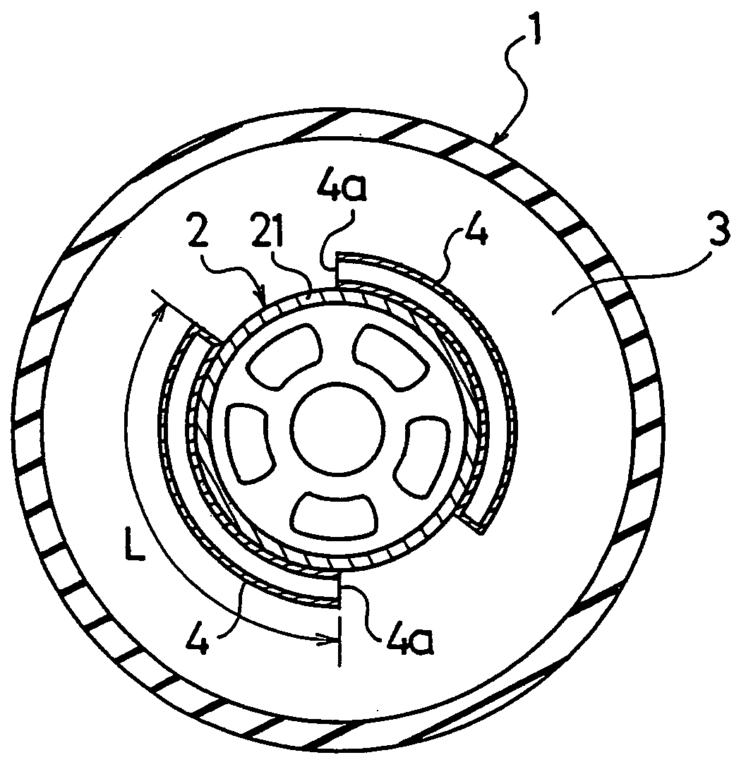
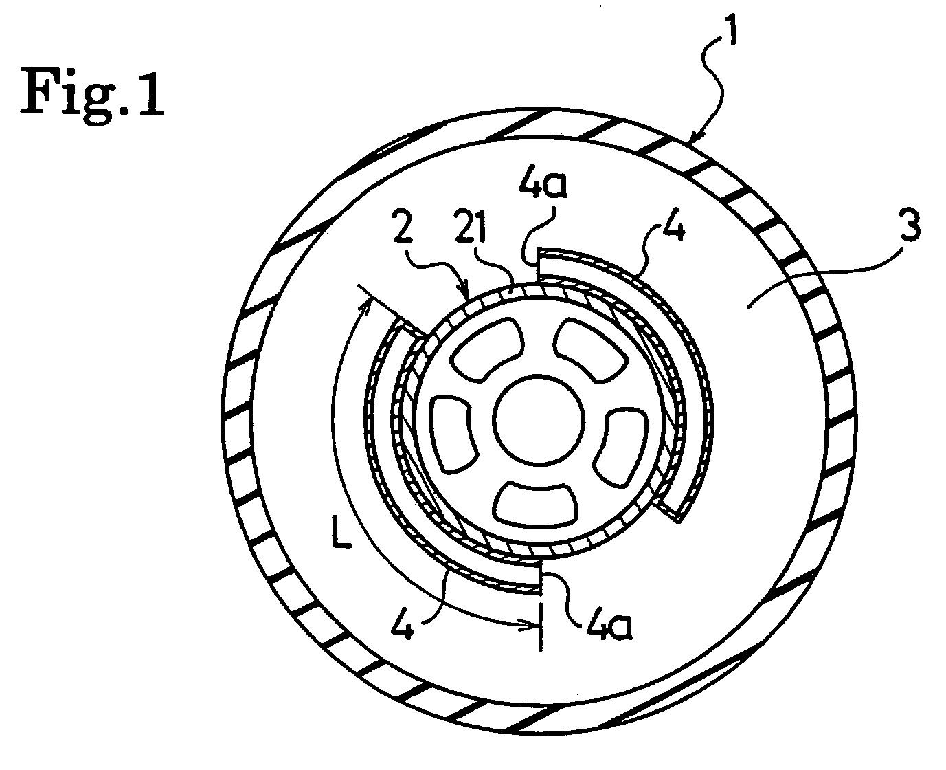
[0030]FIG. 1 schematically shows a tire wheel assembly of the present invention. In FIG. 1, reference numeral 1 denotes a pneumatic tire; and 2, a wheel. This wheel 2 is provided with a rim 21 fitted with the pneumatic tire 1. Additionally, a cavity portion 3 is formed between the pneumatic tire 1 and the rim 21 of the wheel 2. Moreover, in this tire wheel assembly, two tubes 4, 4 are formed so as to open to the cavity portion 3.

[0031]Each of the tubes 4 has one end thereof closed while having a length L approximated to the reference length L0 corresponding to one fourth of a cavity resonance wavelength γ. Opening portions 4a of these tubes 4 are arranged in one arbitrary location on a circumference, or in two locations facing each other across a rotational axis of the tire.

[0032]In the tire wheel assembly configured as described above, vibrat...


PUM


Abstract

Provided is a tire wheel assembly making it possible to effectively reduce cavity resonance noise without causing either negative influence on deformation of a tire or deterioration in rim assembling workability. A tire wheel assembly of the present invention includes a pneumatic tire, and a wheel provided with a rim fitted with the pneumatic tire, and forms a cavity portion between the pneumatic tire and the rim. The tire wheel assembly comprises at least one tube, which has one end thereof closed while having a length of 55% to 110% of a reference length L0 corresponding to one fourth of a cavity resonance wavelength, is provided so as to open to the cavity portion.

Description

TECHNICAL FIELD[0001]The present invention relates to a tire wheel assembly including a pneumatic tire and a wheel. More specifically, the present invention relates to a tire wheel assembly configured to effectively reduce cavity resonance noise.BACKGROUND ART[0002]As one of causes which generate noise in a pneumatic tire, there is cavity resonance noise due to air with which an inside of the tire is filled. This cavity resonance noise is generated due to vibration of air inside the tire, the vibration being caused by vibration of a tread portion because the tread portion vibrates due to irregularities of a road surface.[0003]As a method of reducing noise caused by a cavity resonance phenomenon as described above, there has been proposed one where a time period during which resonance occurs at the same resonance frequency is reduced by changing, along a circumferential direction of the tire, in a cross-sectional area of a closed space formed with a tire and a wheel (for example, ref...

Claims


Application Information

Patent Timeline
IPC IPC(8): B60C5/00B60B21/02B60B21/12B60C19/00
CPCB60B3/005B60B3/02B60B21/00Y10T152/10495B60B21/026B60C19/002Y10T152/10522B60B21/02
Inventor IKEDA, TOSHIYUKITANNO, ATSUSHI
Owner YOKOHAMA RUBBER CO LTD
Why Eureka
Try Eureka