Pneumatic tire, tire mold and method of producing pneumatic tire

Inactive Publication Date: 2009-06-18
YOKOHAMA RUBBER CO LTD
View PDF3 Cites 6 Cited by
  • Summary
  • Abstract
  • Description
  • Claims
  • Application Information

AI Technical Summary

Benefits of technology

[0012]According to the present invention mentioned above, the shallow groove extending between the sipes adjacent in the circumferential direction of the tire is disposed such that the land portion parts sectioned on the opposite sides of the shallow groove are not separated but partially communicate with each other, whereby it is possible to escape air trapped in the parts of the molding surface section sectioned on the opposite sides of the shallow groove molding ridge outside from the one venthole through the communicating part, that is, a communicating part of the tire mold during curing of the tire in the tire mold. Accordingly, while mold production cost is reduced by remarkably reducing the number of ventholes formed in the tire mold, occurrence of curing trouble due to an air pocket can be suppressed.
[0013]By decreasing the number of ventholes, the number of spews formed on the surface of the tire by rubber flown into the bentholes is reduced. Therefore, spew-trimming operation can be facilitated and waste from trimming can also be reduced.
[0014]It is sufficient for the land portion parts to partially communicate with each other. Therefore, the shallow groove can obtain an enough length. Accordingly, reduction of driving stability during turning on a wet road surface can be suppressed.

Problems solved by technology

Therefore, a lot of bentholes must be formed in the mold.
As a result, a production time of the mold is consumed, which creates a problem of an increase in mold production cost.
There is also a problem of troublesome spew-trimming operation and a lot of waste from trimming, because tire producing processes include a process of trimming spews formed on the surface of a tire by rubber flown into bentholes, and when the bentholes increase, the number of the spews increases.

Method used


Image

  • Pneumatic tire, tire mold and method of producing pneumatic tire
  • Pneumatic tire, tire mold and method of producing pneumatic tire
  • Pneumatic tire, tire mold and method of producing pneumatic tire

Examples


example

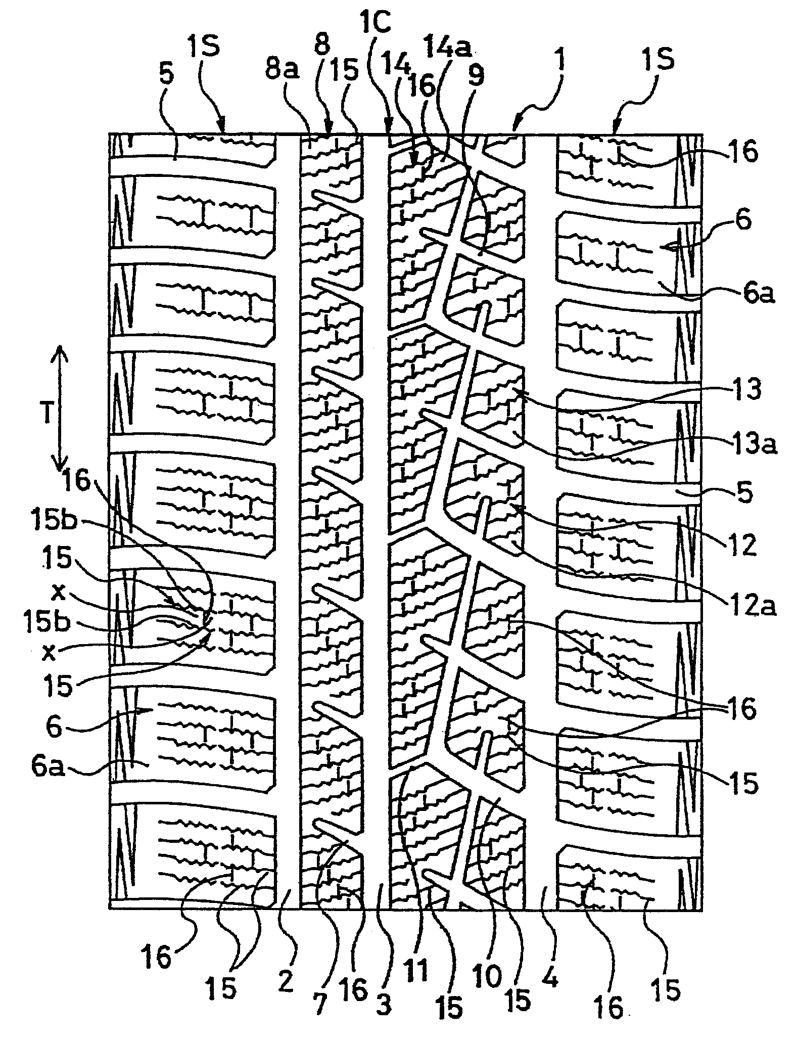
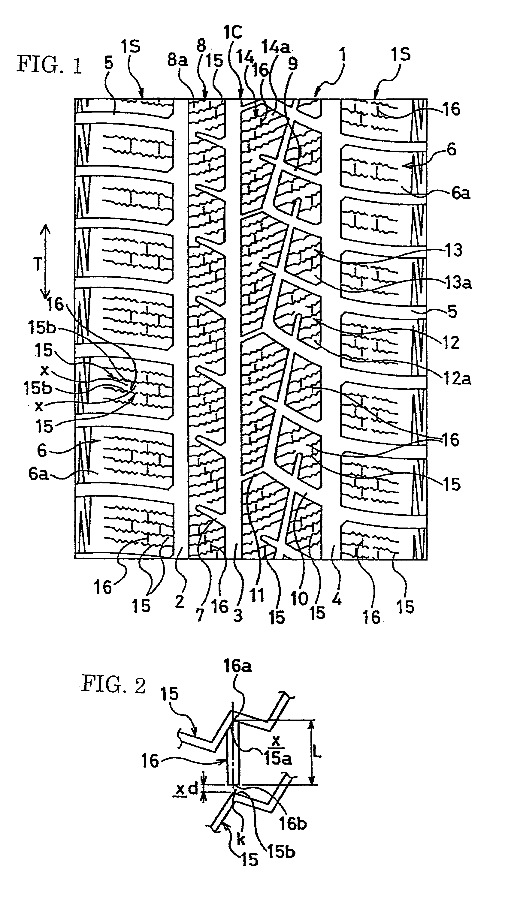
[0083]Prepared were 500 tires according to each of the present invention tires 1 and 2 and conventional tire, each having a tire size of 205 / 55R16, the present invention tires 1 and 2 each having a tread pattern shown in FIG. 1 and the distance d of the communicating part as shown in Table 1, the conventional tire having the same arrangement as the present invention tire 1 except that the shallow grooves had opposite terminal ends communicating with the sipes.

[0084]In each of the prepared tires, the widths of the shallow grooves are 0.8 mm, the depths thereof are 10% of the depths of the main grooves, and the angles of the shallow grooves with respect to the circumferential direction of the tire is 0°.

[0085]In each of tire molds for molding the present invention tires 1 and 2, one venthole is provided near a part through which the parts of each molding surface section sectioned on the opposite sides of a shallow groove molding ridge communicate with each other, and is located within...


PUM

PropertyMeasurementUnit
Lengthaaaaaaaaaa
Fractionaaaaaaaaaa
Fractionaaaaaaaaaa

Abstract

There is provided a pneumatic tire having a shallow groove provided between zigzag sipes adjacent in the circumferential direction of the tire, a tire mold used for production of the pneumatic tire and a method of producing the pneumatic tire with the tire mold, which can reduce production cost of the mold, facilitate trimming operation and decrease waste from trimming while reduction of driving stability during turning on a wet road surface and occurrence of curing trouble are suppressed.The pneumatic tire of the present invention has a tread surface 1 where land portions 6, 8, 12, 13 and 14 are defined by grooves 2, 3, 4, 5, 7, 9 and 10. The land portions 6, 8, 12, 13 and 14 have tread surface sections 6a, 8a, 12a, 13a and 14a, in which a plurality of sipes 15 extending in a zigzag manner in the widthwise direction of the tire are arranged at prescribed intervals in the circumferential direction T of the tire. A shallow groove 16 extends between sipes 15 and 15 adjacent in the circumferential direction T of the tire. The shallow groove 16 is placed such that parts x and x of the land portions sectioned on the opposite sides of the shallow groove 16 are not separated but partially communicate with each other.

Description

TECHNICAL FIELD[0001]The present invention relates to a pneumatic tire, a tire mold used for production of the pneumatic tire and a method of producing the pneumatic tire with the tire mold, and more particularly, to a pneumatic tire, a tire mold and a method of producing the pneumatic tire capable of reducing production cost of the mold and facilitating trimming operation while reduction of driving stability during turning on a wet road surface and occurrence of curing trouble are suppressed.TECHNICAL BACKGROUND[0002]A conventional pneumatic tire used in winter has sipes in land portions such as blocks and ribs. The sipes, which extend in the widthwise direction of the tire in a zigzag path, are provided at prescribed intervals in the circumferential direction of the tire. High on-ice performance is achieved by an edge effect arising from the sipes (see a patent document 1, for example).[0003]In the above pneumatic tire, a technique of providing a shallow groove between zigzag sipe...

Claims


Application Information

Patent Timeline
IPC IPC(8): B60C11/12
CPCB29D30/0606B29D2030/0613B60C11/12Y10S152/03B60C2011/1231B60C2011/0374B60C11/0304
Inventor SAKAI, TOMONORI
Owner YOKOHAMA RUBBER CO LTD
Why Eureka
Try Eureka