Staged Actuation Shear Sub for Use Downhole

Inactive Publication Date: 2009-06-11
EXTREME ENERGY SOLUTIONS
View PDF11 Cites 13 Cited by
  • Summary
  • Abstract
  • Description
  • Claims
  • Application Information

AI Technical Summary

Benefits of technology

[0011]In accordance with a first aspect of the invention, there is provided a shear assembly for use downhole, the shear assembly comprising: a mandrel for integration within a work string; a shear sleeve slideable with respect to the mandrel to actuate a work string function; setting means for setting the shear sleeve in a fixed position with respect to the mandrel, the setting means shearable by application of a threshold force to the work string, thereby actuating the work string function; and a dampening subassembly operatively associated with the mandrel and with the shear sleeve for slowing the sliding momentum of the shear sleeve with respect to the mandrel following shearing of the setting means.
[0016]In an embodiment, the dampening subassembly reduces the abutment force by at least 10,000 pounds force.

Problems solved by technology

From time to time, the tool may become lodged within the wellbore due to this accumulation of debris.
Unfortunately, these loosening methods often fail, requiring the bottom hole assembly to be sheared from the tubing string and fished out of the well.
Such fishing operations are expensive and time consuming, as an independent contractor must transport specialized equipment to the site in order to fish the bottomhole assembly from the wellbore.
Once the tubing string has been sheared from the fishneck, the fishneck may remain inaccessible due to further accumulation of debris during shearing and removal of the tubing string.
To date, a shear-actuated wash mechanism has not been incorporated within a work string above a bottom hole assembly for use in freeing the bottom hole assembly should it become lodged within the wellbore.
Moreover, it has not to date been possible to include two tension shear-actuated devices within a work string in close proximity, or with similar shear thresholds.
Should a second tension-shearable element be present in close proximity within the work string, the inertial force of the moving parts immediately subsequent to the first shearing event may be great enough to exceed the second shear threshold unintentionally.
Due in part to the above-noted limitations associated with current shear devices, typically only one tension shear-actuated function is useful within a tubing string.
As such, a shear sub is usually limited to use as a last resort mechanism by which the operator may separate the tubing string from the equipment in an emergency or otherwise problematic situation.

Method used


Image

  • Staged Actuation Shear Sub for Use Downhole
  • Staged Actuation Shear Sub for Use Downhole
  • Staged Actuation Shear Sub for Use Downhole

Examples


Embodiment Construction

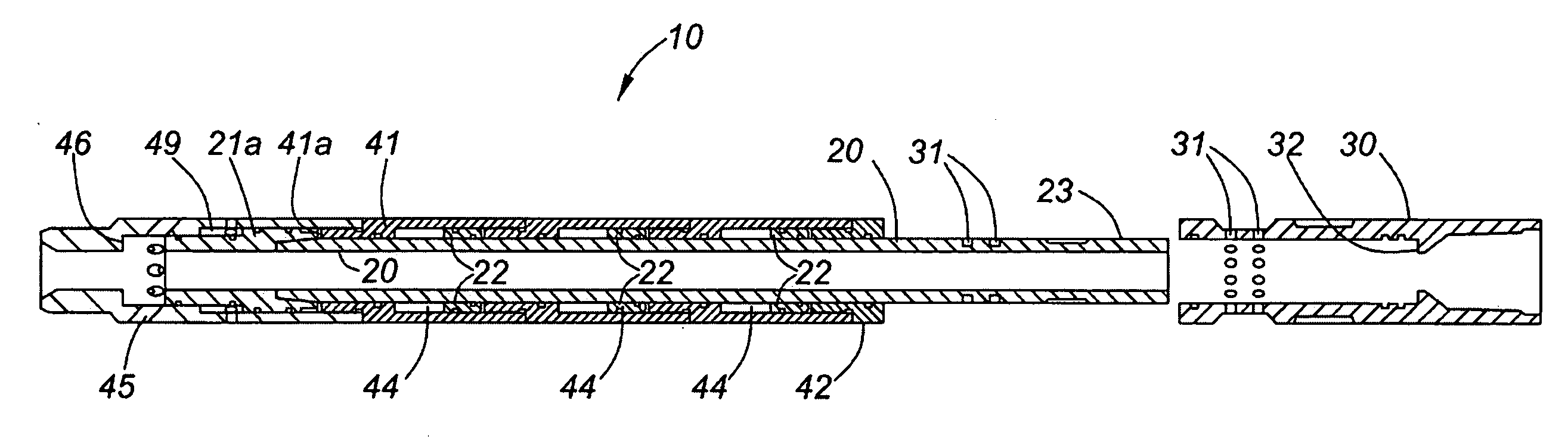
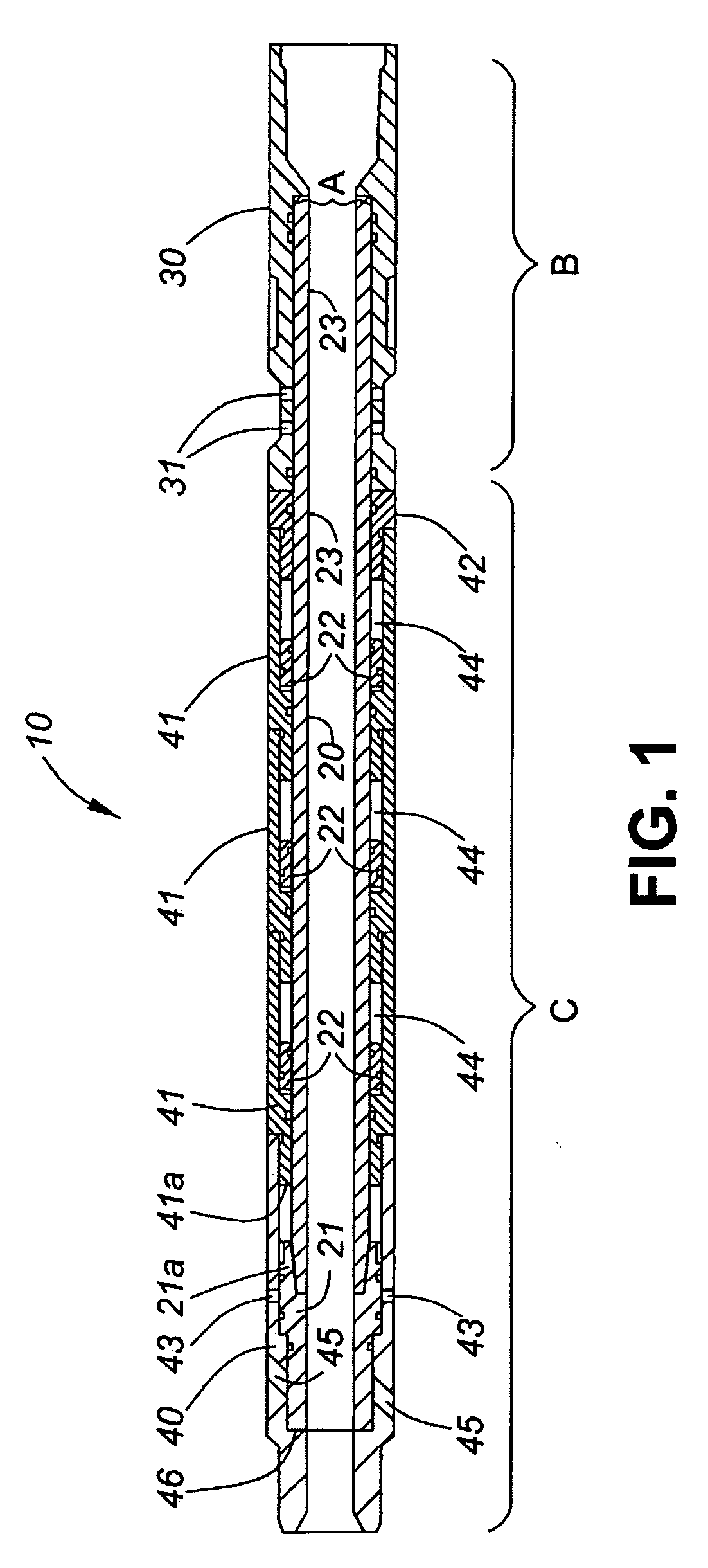
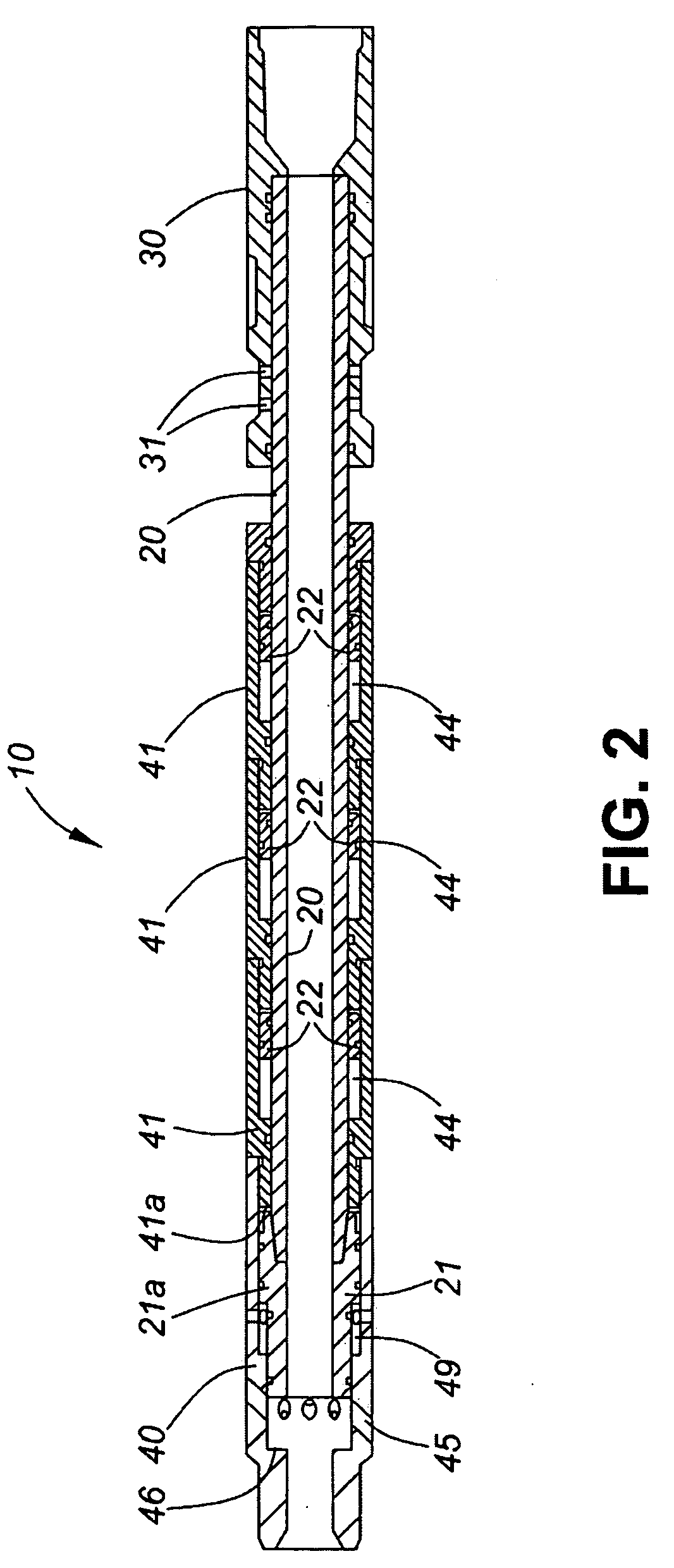
[0028]Generally, the present invention provides a downhole shear assembly for actuating a work string tool or process. Specifically, the device incorporates dampening means for minimizing post-shear inertial force within the work string and related equipment. Minimizing the post-shear inertial force prevents damage or premature actuation of sensitive components within the work string, and permits more precise control of forces applied to work string tubing and equipment. This additional degree of precision in force application permits an additional shear point to be incorporated within the assembly for actuation of a second process or function, the second shear mechanism having a higher actuation force threshold. In such dual shear devices, a first shear sleeve may be designated for initiation of a downhole process or to actuate a downhole tool, while the second shear sleeve (set to a higher force threshold) may be assigned to initiate a second possibly independent, process. For exa...


PUM


Abstract

A shear assembly used downhole to actuate a work string function includes a dampening subassembly to dampen the momentum of moving parts following shearing to avoid excessive acceleration and resulting jarring forces within the work string. A dual shear assembly is provided, in which the dampening subassembly prevents inertial force resulting from a first shear from exceeding the threshold for actuating the second, higher threshold, shear mechanism thereby allowing more precise control of the forces applied to the work string to prevent premature shearing of the second shear mechanism. In a specific embodiment, the dampening subassembly is a hydraulic dampening subassembly. The dual shear assembly may be used, for example, to first open a wash port above a tool lodged within the wellbore to loosen debris above the lodged tool, and then to shear the tool from the work string if necessary.

Description

CROSS-REFERENCE TO RELATED APPLICATIONS[0001]The present invention claims the benefit of U.S. Provisional Patent Application Ser. No. 61 / 012,457 entitled “Staged Actuation Shear Sub for Use Downhole” filed Dec. 9, 2007.FIELD OF THE INVENTION[0002]The present invention relates generally to tools for use within a wellbore. More particularly, the present invention relates to a shear assembly for integration within a work string.BACKGROUND OF THE INVENTION[0003]During use of downhole equipment within a wellbore, sand and other debris may enter the wellbore and accumulate above the bottom hole assembly. From time to time, the tool may become lodged within the wellbore due to this accumulation of debris. Various means of attempting to loosen lodged equipment are known, which generally include pulling (such as the controlled pulling taught by U.S. Pat. No. 7,249,633), vibrating, or reciprocating the bottom hole assembly within the wellbore until same is freed of debris. Unfortunately, thes...

Claims


Application Information

Patent Timeline
IPC IPC(8): E21B29/00
CPCE21B23/00E21B37/00E21B31/107
Inventor KRATOCHVIL, ROBERT BOHUSLAVKIRK, SCOTT OLIVERSCHOFIELD, DANIELSMOLCIC, DARKO
Owner EXTREME ENERGY SOLUTIONS
Why Eureka
Try Eureka