
Battery system

a battery system and battery technology, applied in the field of battery systems, can solve the problems of reducing the difference in temperature, and reducing the service life of the cell, so as to reduce the pressure loss, simplify the entire structure, and lighten the weight

Inactive Publication Date: 2009-06-04
SANYO ELECTRIC CO LTD
View PDF8 Cites 65 Cited by
  • Summary
  • Abstract
  • Description
  • Claims
  • Application Information

AI Technical Summary

Benefits of technology

The present invention provides a battery system with a simplified structure that can effectively cool the battery cells. The battery system includes a battery block with multiple battery cells arranged in an ideal array, with cooling gaps between the cells. A forced gas blower is used to cool the battery cells through the cooling gaps. The battery system also includes an outer duct and an intermediate duct that allow the cooling gas to flow in a parallel relationship. The battery system is designed to have a reduced temperature difference between the cells, which can extend the service life of the battery. The outer casing of the battery system can be reinforced with a ridge to reduce pressure loss and reinforce the outer duct. The battery system can also have a simplified structure and a reduced weight.

Problems solved by technology

The battery systems described in the above publications suffer a drawback that when the number of layered rectangular / prismatic cells increases, it becomes difficult to cool all the cells at a uniform temperature, that is, with a reduced difference in temperature.
This is because, when a temperature difference occurs to the cells, the residual capacities of the cells become uneven, and thus a cell's service life becomes shortened.
When a difference occurs in the residual capacity, a cell with a larger amount of residual capacity is liable to be over-charged, while a cell with a smaller amount of residual capacity is liable to be over-discharged, with such a state causing the service life of the battery system to be shortened.
Like in the case of a hybrid car, where a multitude of cells are layered to be used for charging and discharging the cells at a large amount of electric current, this kind of battery system involves a very high cost of manufacture, so that it is particularly important how to elongate the battery's service life.
In particular, a battery system using a large number of cells involves a higher cost of manufacture, it is required to elongate the service life of the battery system.
Notwithstanding, when a multitude of cells are layered, the battery system will characteristically encounter a larger temperature difference and accordingly will shorten the service life of battery system.

Method used


Image

  • Battery system
  • Battery system
  • Battery system

Examples


Embodiment Construction

)

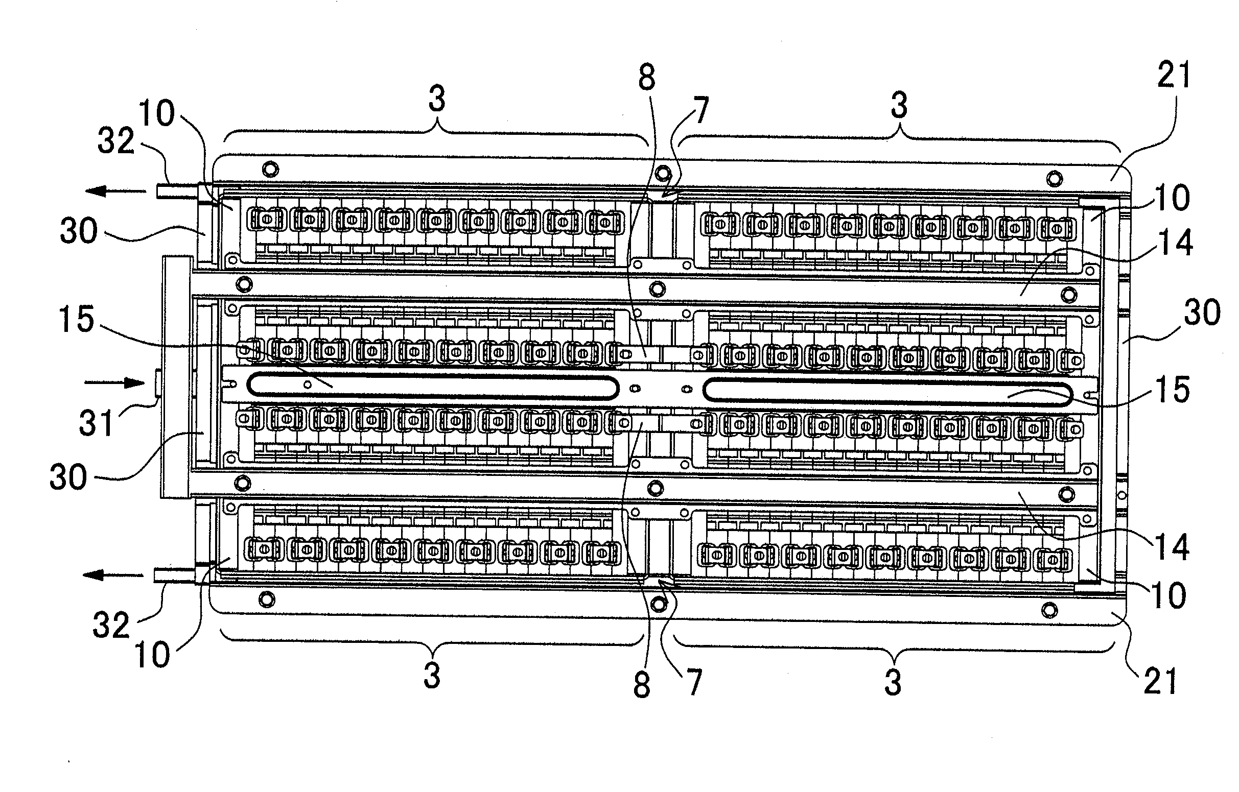
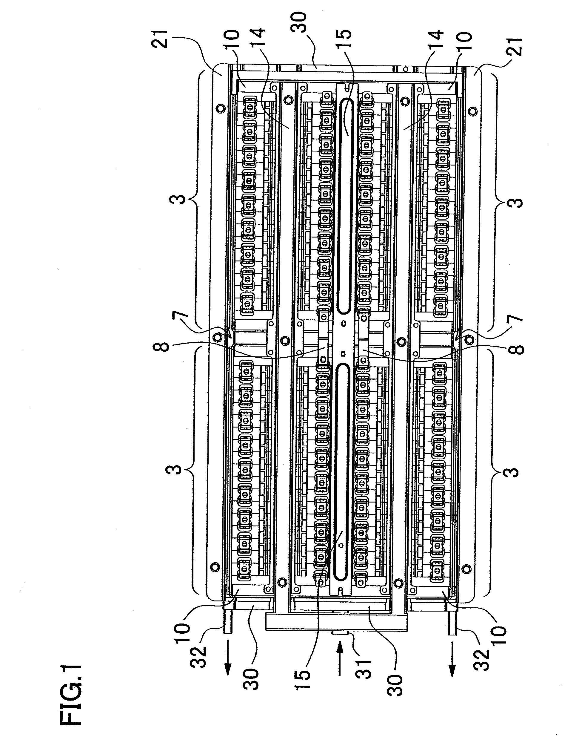
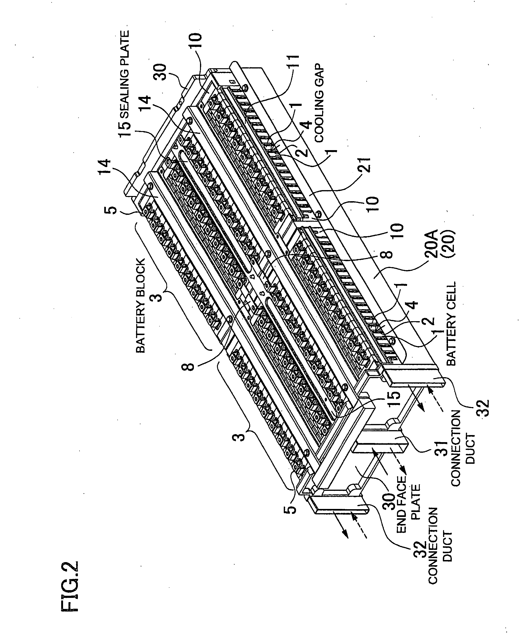
[0041]FIG. 1 through FIG. 10 show (a battery system in accordance with) a first embodiment of the present invention; FIG. 12 through FIG. 14 show (a battery system in accordance with) a second embodiment (of the present invention); and FIG. 15 and FIG. 16 show a battery system as a referential case. The battery system shown in these embodiments are optimal as a power source to be primarily used with a hybrid car traveling by means of both of an engine and a motor, and with an electric vehicle such as an electric car traveling by means of a motor alone. It should be noted, however, that the battery system can also be used with a vehicle other than the hybrid car or the electric car, and can also be used for an application, other than the electric vehicle, where a large power output is required.

[0042]The battery system shown in the following embodiment includes: a battery block 3 in which the battery cells 1, composed of a plurality of rectangular / prismatic cells, are layered in a st...


PUM

PropertyMeasurementUnit
temperatureaaaaaaaaaa

Abstract

A battery system includes: a battery block defining a cooling gap between battery cells composed of a plurality of rectangular / prismatic cells; and a gas blower forcibly blowing the gas through the gap in the block. The block, set in two separate arrays, is provided therebetween with an intermediate duct connected to each of the gaps. An outer duct is provided outside the block set in two separate arrays, and the plurality of gaps are parallel-connected between the outer duct and the intermediate duct. The gas blower forcibly blows the gas from the intermediate duct to the outer duct, and the gas forcibly blown is branched from the intermediate duct to be blown through each of the gaps to cool the cells. The gas having passed through the gaps and cooled the cells is collected at and exhausted from the outer duct.

Description

BACKGROUND OF THE INVENTION[0001]1. Field of the Invention[0002]The present invention relates to a battery system in which battery cells composed of a plurality of rectangular / prismatic cells are layered and interconnected, and gas is forcibly blown, for a cooling purpose, between the battery cells.[0003]2. Description of the Related Art[0004]Battery systems, in which a plurality of rectangular / prismatic cells are layered, have been developed as described in JP-2001-23702A and JP-H8-32129A (1996).[0005]In the battery system disclosed in JP-2001-23702A, a multitude of rectangular / prismatic cells are layered to form a battery block, with a spacer being disposed between the cells in a manner of defining a cooling gap. A cooling medium such as air is blown through the cooling gap defined by the spacer. In this battery system, the multitude of layered rectangular / prismatic cells are cooled by a cooling medium such as air blown through the cooling gap. On the other hand, in the battery sy...

Claims


Application Information

Patent Timeline
Patent Type & Authority Applications(United States)
IPC IPC(8): H01M10/50H01M2/00B60K11/06H01M10/60H01M10/613H01M10/617H01M10/625H01M10/647H01M10/651H01M10/6563H01M10/658H01M50/209H01M50/264H01M50/293
CPCH01M2/1077H01M2/18H01M10/0525H01M10/5004Y02T10/7011H01M10/5032H01M10/5055H01M10/5059H01M10/5067H01M10/5016H01M10/625H01M10/6563H01M10/647H01M10/6557H01M10/6555H01M10/613Y02E60/10H01M50/293H01M50/209H01M50/264
Inventor OKADA, WATARUSHIMIZU, HIDEONAKAMURA, SHINSUKE
Owner SANYO ELECTRIC CO LTD
Learn More