Electrostatic deflector

a technology of electrostatic deflectors and electrodes, applied in the manufacture of electric discharge tubes/lamps, instruments, heat measurement, etc., can solve the problems of excessive working labor, difficult to arrange electrodes in equally spaced forms, and insufficient working labor for efficient manufacture of electrostatic deflectors, etc., to achieve easy and accurate manufacture.

Inactive Publication Date: 2009-06-04
KK TOPCON
View PDF13 Cites 0 Cited by
  • Summary
  • Abstract
  • Description
  • Claims
  • Application Information

AI Technical Summary

Benefits of technology

[0014]In the present invention, therefore, first assembling the electrode material into an insulating member integrally without separating the electrode material into each electrode member and by forming slits therein, and then splitting the electrode material allows an electrostatic deflector to be manufactured easily and very accurately without using a member for positioning the electrostatic deflector.

Problems solved by technology

Such an electrostatic deflector as described in Japanese Patent Laid-open No. 2-100250, however, has a problem in that since four sector-form electrodes must be arranged with rod-shaped structures as their supporting columns inside a cylindrical insulator, too great a deal of working labor is required for efficient manufacture of the electrostatic deflector.
Also, such electrostatic deflectors as described in Japanese Patent Laid-open Nos. 8-171881, 4-174510, 2-123651, and 10-261376 have a problem in that since electrodes must be mounted in or on an electrode supporter by means of bonding or the like, a great deal of working labor is required and the electrodes are extremely difficult to arrange in equally spaced form with respect to an electron beam so as not to cause a disturbance of a magnetic field and so as not to bring the electrodes into contact with one another.
In addition, such an electrostatic deflector as described in Japanese Patent No. 5-29201, however, has a problem in that since independent insulators are fittingly inserted into outer insulating grooves and then bonded onto the inner walls thereof, too great a deal of working labor is required for efficient manufacture of the electrostatic deflector.

Method used


Image

  • Electrostatic deflector
  • Electrostatic deflector
  • Electrostatic deflector

Examples


Embodiment Construction

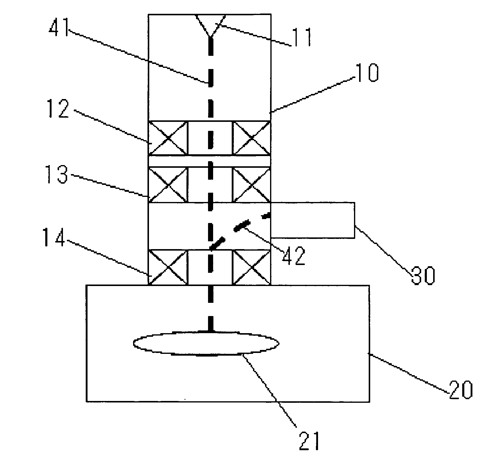
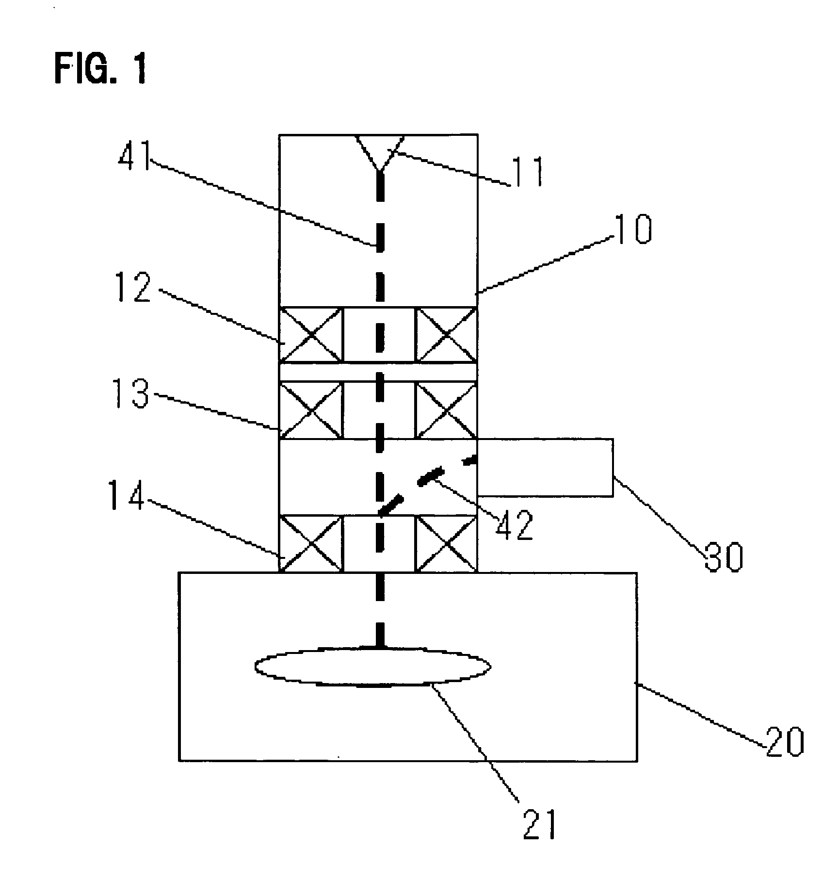
[0022]A method of manufacturing an electrostatic deflector according to an embodiment of the present invention will be described below. The electrostatic deflector according to the invention is used in, for example, the scanning electron microscope shown in FIG. 1. This scanning electron microscope, after generating an electron beam 41 from an electron beam generator 11 provided in an upper section of a lens barrel 10, first deflects the electron beam via alignment coils 12 (a first deflector) and stigmatic coils 13 (a second deflector). Next, the scanning electron microscope adjusts a magnification using objective lens coils 14 (a magnification controller), and scans a sample 21. After this, the scanning electron microscope activates a detector 30 to detect an electrically charged particle 42 generated from the sample 21, such as a secondary electron or backscattered electron, and displays an image of the sample at an image display device not shown, such as a monitor. The image of ...


PUM


Abstract

An electrostatic deflector that can be manufactured easily and very accurately without using a member for positioning is provided. After multiple slits 81d to 88d have been formed in the same direction as that of the bus bar of an approximately conical electrode material 100 whose large-diameter section is formed with flange portions 81a to 88a for installation on an insulator 90, each of the flange portions is coupled with the insulator 90, then the electrode material 100 is cut along extension lines of the slits 81d to 88d, and thus, multiple electrode members electrically isolated from one another are formed.

Description

[0001]This application is a division of U.S. patent application Ser. No. 11 / 430,195 filed May 9, 2006, and claims priority of Japanese patent application No. 2005-286918 fled Sep. 30, 2005, each of which is incorporated herein by reference.BACKGROUND OF THE INVENTION[0002]The present invention relates generally to deflectors for deflecting electron beams, ion beams, and other electrically charged beams. More specifically, the invention relates to an electrostatic deflector for use in electron beam exposure apparatuses, ion implantation apparatuses, electron microscopes, and the like.[0003]Some of traditionally known deflectors are outlined below. Japanese Patent Laid-open No. 2-100250 describes an electrostatic deflector having four sector-form electrodes arranged, with rod-shaped structures as their supporting columns, inside a cylindrical insulator. Also, Japanese Patent Laid-open No. 8-171881 describes an electrostatic deflector constructed by machining eight split electrode piec...

Claims


Application Information

Patent Timeline
Patent Type & Authority Applications(United States)
IPC IPC(8): G21K1/08
CPCH01J37/147H01J2209/00H01J37/1477
Inventor KAMETANI, TAKASHIINOUE, MASAHIRO
Owner KK TOPCON
Why Eureka
Try Eureka