
Method for producing retardation film

a retardation film and film technology, applied in the field of retardation film production, can solve problems such as difficulty in producing retardation film, and achieve the effect of accurate and easy manufacturing

Active Publication Date: 2015-08-13
ZEON CORP
View PDF2 Cites 2 Cited by
  • Summary
  • Abstract
  • Description
  • Claims
  • Application Information

AI Technical Summary

Benefits of technology

The present invention provides a method for making a retardation film that can easily and accurately meet certain requirements. This can result in a larger area of the film that meets certain conditions. The technical effect is the ability to produce a high-quality retardation film with a specific relation between the different directions of the film.

Problems solved by technology

However, it is difficult to produce the retardation film having a large area by the producing method described in the Patent Document 4.

Method used


Image

  • Method for producing retardation film

Examples


example 3

Producing Example 3

[0099]A laminated film 3 being 1350 mm in width and 180 μm in thickness composed of the polycarbonate resin layer (layer A: 10 μm) and the styrene-maleic anhydride copolymer resin layer (layer B: 170 μm) was obtained in the same manner as in PRODUCING EXAMPLE 1, except that the thickness of layer A was adjusted to 10 μm and the thickness of layer B was adjusted to 170 μm.

example 4

Producing Example 4

[0100]A laminated film 4 being 1350 mm in width and 180 μm in thickness composed of the polycarbonate resin layer (layer A: 80 μm) and a polystyrene resin layer (layer B: 90 μm) was obtained in the same manner as in PRODUCING EXAMPLE 1, except that the polystyrene resin (made by Japan Polystyrene Inc., HF44, a deflection temperature under load is 73° C.) was used in place of Dylark D332, the thickness of layer A was adjusted to 80 μm and the thickness of layer B was adjusted to 90 μm.

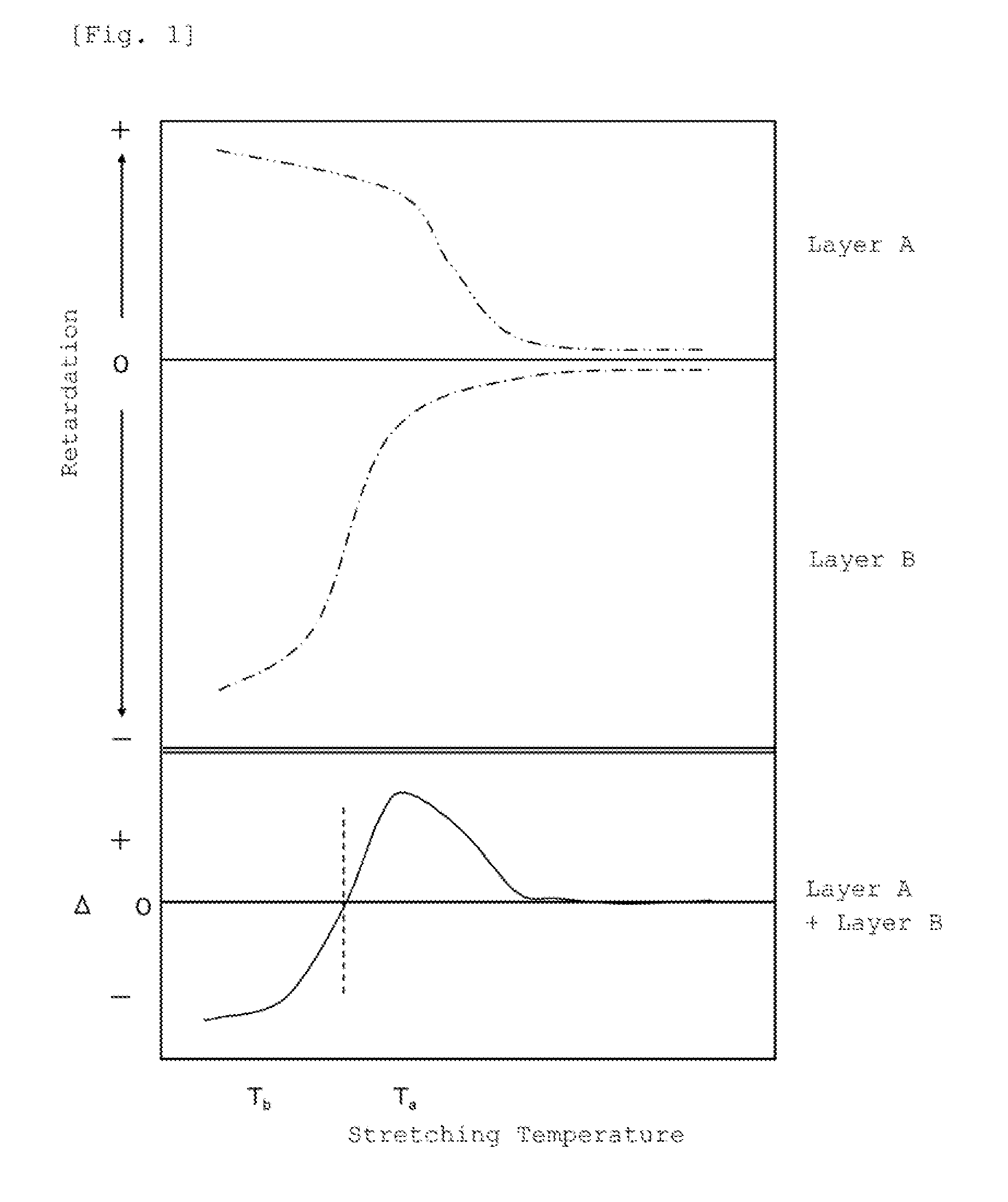
[0101]The laminated films 1 to 4 were uniaxially stretched by 1.25 times of stretching ratio in various temperatures in a longitudinal direction of the film. Table 1 shows the lag in a phase of which linearly polarized light entering vertically into the film plane and having an oscillating surface of an electric vector in an X-Z plane against linearly polarized light entering vertically into the film plane and having an oscillating surface of an electric vector in a Y-Z plane, in whic...

example 1

[0104]The laminated film 1 obtained in PRODUCING EXAMPLE 1 was supplied to a longitudinal uniaxially stretching machine, and the film was stretched in a longitudinal direction at a stretching temperature of 145° C. by a stretching magnification of 1.5 times.

[0105]Then, the stretched film was supplied to the tenter stretching machine, the film was stretched in a transverse direction at a stretching temperature of 130° C. by a stretching magnification of 1.25 times, and a retardation film 1 was obtained. The evaluation results are shown in Table 2.


PUM

PropertyMeasurementUnit
incident angleaaaaaaaaaa
deflection temperatureaaaaaaaaaa

Abstract

A method for producing a retardation film comprising the steps of: (a) uniaxially stretching an original film for producing retardation film in one direction at either a temperature T1 or T2; and then (b) uniaxially stretching the film stretched in the step (a) in a direction perpendicular to the above-mentioned direction of stretching at a temperature T2 or T1 different from the above-mentioned temperature, in which the original film for producing retardation film has a characteristic that a phase of linearly polarized light entering vertically into the film plane and having an oscillating surface of an electric vector in an X-Z plane against linearly polarized light entering vertically into the film plane and having an oscillating surface of an electric vector in a Y-Z plane lags by uniaxially stretching in the direction of the X axis at a temperature T1, and leads by uniaxially stretching in the direction of the X axis at a temperature T2 different from the above-mentioned temperature T1, in which the X axis is an uniaxially stretching direction, the Y axis is a direction perpendicular to the uniaxially stretching direction in the film plane, and the Z axis is a direction of a thickness of the film.

Description

[0001]This application is a Continuation of copending application Ser. No. 12 / 371,317, filed on Feb. 13, 2009, which claims priority under 35 U.S.C. §119(e) to U.S. Provisional Application No. 61 / 080,945, filed on Jul. 15, 2008, and under 35 U.S.C. §119(a) to Application No. 2008-033782, filed in JAPAN on Feb. 14, 2008, all of which are hereby expressly incorporated by reference into the present application.TECHNICAL FIELD[0002]The present invention relates to a method for producing a retardation film. More particularly, the present invention relates to a method for producing a retardation film suitable for birefringence compensation of a liquid crystal display device.BACKGROUND OF THE ART[0003]To decrease dependence of a color tone in a liquid crystal display device on an angle, a retardation film which satisfies a relation of 0.92≦R40 / Re≦1.08, in which Re is a retardation value at an incident angle of 0 degrees, and R40 is a retardation value at an incident angle of 40 degrees, or...

Claims


Application Information

Patent Timeline
Patent Type & Authority Applications(United States)
IPC IPC(8): B29D11/00B29C55/14G02B5/30C08J5/18B32B7/023
CPCB29D11/00788C08J5/18B29C55/14G02B5/3083B29K2995/0034C08J2325/06C08J2369/00B29K2025/06B29K2069/00B29D11/00644B29C55/023B32B27/08G02F1/133634B32B23/08B32B23/20B32B27/18B32B27/20B32B27/22B32B27/286B32B27/302B32B27/304B32B27/306B32B27/308B32B27/32B32B27/36B32B27/365B32B2264/0235B32B2264/025B32B2264/102B32B2264/104B32B2270/00B32B2307/306B32B2307/40B32B2307/42B32B2307/516B32B2307/558B32B2307/71B32B2307/744B32B2457/202B32B2264/04Y10T428/2495Y10T428/31507B32B7/023G02F1/13363G02B5/30
Inventor HATANO, TAKU
Owner ZEON CORP
Learn More