Fiber Cure with Extended Irradiators

Active Publication Date: 2009-06-04
CORNING INC
View PDF6 Cites 22 Cited by
  • Summary
  • Abstract
  • Description
  • Claims
  • Application Information

AI Technical Summary

Benefits of technology

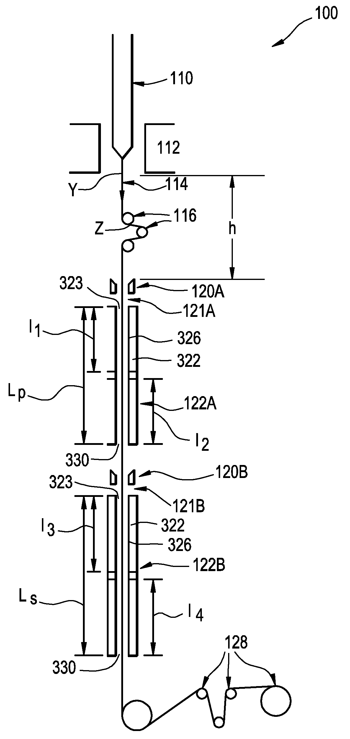
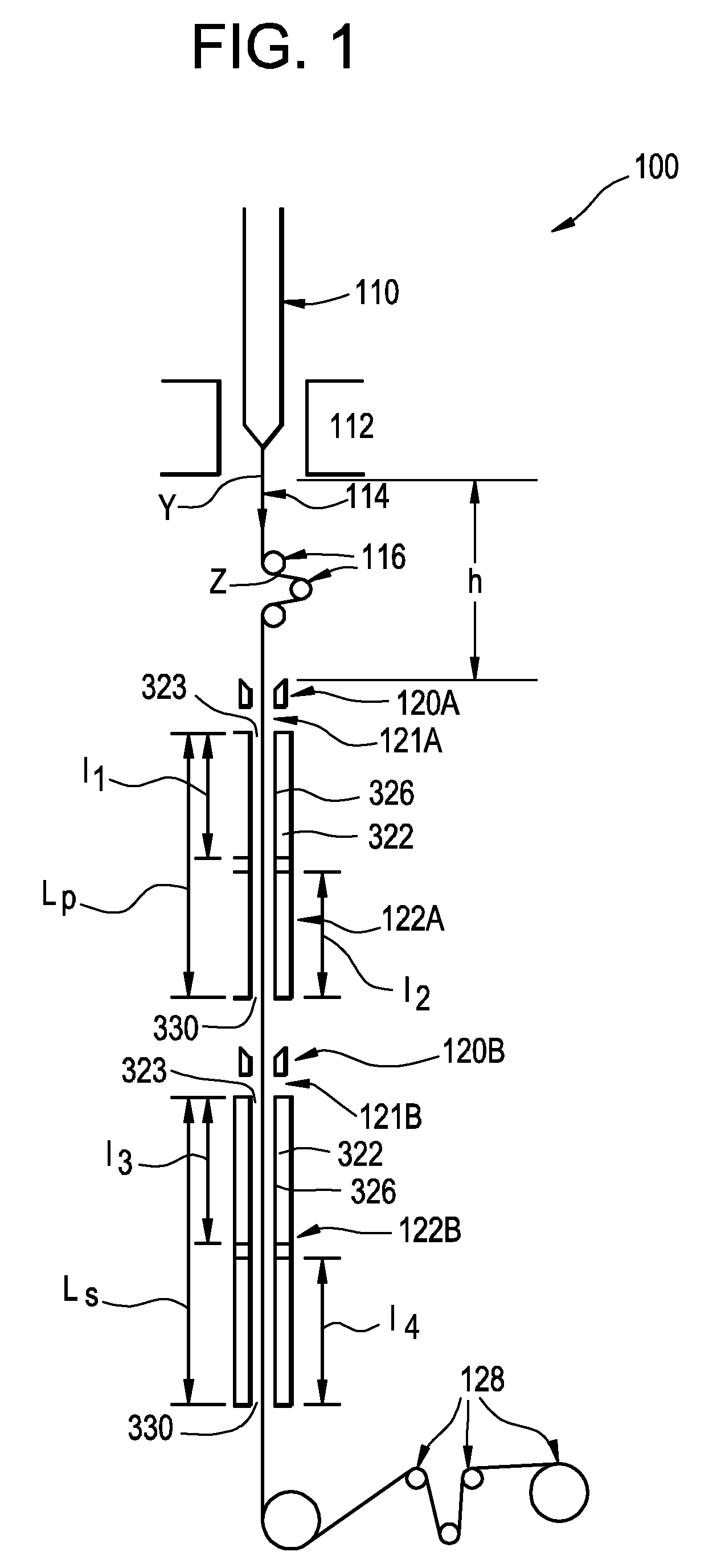
[0020]Higher draw rates reduce the cost of manufacturing optical fiber. When coating an optical fiber it is important to produce, at high draw rates, uniform, strong coatings that can protect the fiber core. However, when a freshly coated fiber is not provided with a sufficient dwell time inside irradiators (for example, when the fiber is drawn too fast through the irradiation devices), the fiber coating may not cure sufficiently and the fiber will suffer from defects such as delaminating coatings, non-uniform coatings, weaker coatings, or undesirable changes in fiber's optical parameters. To combat these defects, the optical fiber is irradiated in accordance with the invention by maintaining the optical fiber within an irradiation zone for a sufficient time to be cured. One advantage of the present invention is that it enables a faster draw speed and provides a longer irradiation zone(s) to sufficiently cure the fiber coating(s).
[0021]The present invention includes improved methods for irradiating drawn optical fibers, to reduce defects that are associated insufficient coating cure. As used herein, “irradiating” exposing a coated fiber is moved to irradiation, preferably with UV light, which at least partially cures the coating. As will be better understood from the description that follows, the methods and apparatus of the present invention may allow for relatively high speed, high tension formation of drawn, doped, optical glass fibers having well cured coating as compared to prior art methods for making fibers.
[0022]To achieve the foregoing, an embodiment of the present invention includes a system and a method for producing an optical fiber including drawing the fiber from a heated glass source, and contacting the bare optical fiber with a region of fluid cushion of a fluid bearing and redirecting the bare optical fiber along at least a second pathway as the bare optical fiber is drawn across the region of fluid cushion.
[0023]According to further embodiments of the invention, a method of manufacturing an optical fiber at high speed is provided that comprises the steps of drawing the optical fiber from a heated glass supply, such as optical fiber preform, at a draw rate of greater than or equal to 10 m / s, preferably greater than or equal to 20 m / s, and even more preferably greater than or equal to 30 m / s, followed by cooling step wherein the optical fiber is preferably cooled to 200° C. or less, more preferably to less than 100° C., and even more preferably to less than 80° C.
[0024]As used herein, the term “irradiation zone” refers to an area downstream from a draw furnace where coated optical fiber is irradiated to at least partially cure the fiber coating(s), for example by UV light. In a preferred embodiment, the average irradiation rate (also referred as average power herein) of the fiber in the irradiation zone may be less than 400 W / cm, including less than 300 W / cm, preferably more than 80 W / cm, for

Problems solved by technology

However, this technique provides significant impediments to improving and modifying production of the optical fiber.
For example, the equipment associated with linear production of optical fibers is usually aligned in a top to bottom fashion thereby making it difficult to add or modify the process without adding height to the overall system.
Such impediments cause significant costs in order to provide modifications or updates to optical fiber production systems and facilities.
For example, it is difficult to increase the draw speed of the fiber, because the fiber spends less time in UV irradiators that cure fiber coating.
However, adding more irradiators or larger irradiators to the linear production system is difficult.
There is typically little space available for adding additional irradiators (to accommodate a fiber that travels faster through the irradiator), without adding height to the overall system.
Because adding height to an existing system can add significant cost to the system, fiber draw systems in which space is available for additional irradiators without necessitating an increase in overall system height are desired.

Method used


Image

  • Fiber Cure with Extended Irradiators
  • Fiber Cure with Extended Irradiators
  • Fiber Cure with Extended Irradiators

Examples


Embodiment Construction

[0018]Reference will now be made in detail to the present preferred embodiment(s) of the invention, examples of which are illustrated in the accompanying drawings.

[0019]The invention provides new system(s) and method(s) for producing optical fibers along nonlinear paths through the use of fluid bearings. Embodiments of the present invention are herein described in detail in connection with the drawings of FIGS. 1-5, wherein like numbers indicate the same or corresponding elements throughout the drawings.

[0020]Higher draw rates reduce the cost of manufacturing optical fiber. When coating an optical fiber it is important to produce, at high draw rates, uniform, strong coatings that can protect the fiber core. However, when a freshly coated fiber is not provided with a sufficient dwell time inside irradiators (for example, when the fiber is drawn too fast through the irradiation devices), the fiber coating may not cure sufficiently and the fiber will suffer from defects such as delamin...


PUM

PropertyMeasurementUnit
Lengthaaaaaaaaaa
Lengthaaaaaaaaaa
Lengthaaaaaaaaaa

Abstract

A method for producing an optical fiber that includes a method for producing an optical fiber, said method comprising: (i) drawing a bare optical fiber from a preform along a first pathway at a rate of at least 10 m / sec; (ii) contacting said bare optical fiber with a region of fluid in a fluid bearing and redirecting said bare optical fiber along a second pathway as said bare optical fiber is drawn across said region of fluid cushion; (iii) coating the bare optical fiber; and (iv) irradiating said coated fiber in at least one irradiation zone to at least partially cure said coating, while subjecting the optical fiber to UV light.

Description

[0001]This application claims the benefit of priority under 35 U.S.C. §119 (e) of U.S. Provisional Application Ser. No. 61 / 004,676 filed on Nov. 29, 2007.BACKGROUND OF THE INVENTION[0002]1. Field of the Invention[0003]The present invention relates to methods and apparatus for forming optical fiber and more particularly, to methods and apparatus for forming optical fiber having improved characteristics.[0004]2. Technical Background[0005]Optical fibers have acquired an increasingly important role in the field of communications, frequently replacing existing copper wires. This form of transmission is done by sending a beam of light through an optically clear fiber. Because interference with the light beam or its partial loss during the transmission must be at a minimum to make the use of optical fibers a successful communications technology, the optical fibers must be protected from any environment which will cause loss of signal or distortion of the signal. Coating the fibers is one s...

Claims


Application Information

Patent Timeline
IPC IPC(8): C03B37/02C03B37/01
CPCC03B37/02718C03B37/032C03C25/12C03B2205/55C03B2205/42Y02P40/57
Inventor FILIPPOV, ANDREY V.REDING, BRUCE WARRENSHEPARD, BRADLEY KENTTUCKER, DAVID ANDREW
Owner CORNING INC
Why Eureka
Try Eureka