Hand-held power tool with a pneumatic percussion mechanism

Active Publication Date: 2009-05-28
HILTI AG
View PDF7 Cites 18 Cited by
  • Summary
  • Abstract
  • Description
  • Claims
  • Application Information

AI Technical Summary

Benefits of technology

[0010]With a bore, the bore containing body of the percussion piston is substantially lighter than a (initial) solid body at a given length and guide diameter. The bore is formed in an usually machined percussion piston having a solid body by a technologically simple manufacturing process, in particular, by drilling. This permits to technologically simple vary the mass of the percussion piston (in different percussion mechanisms). A bore which has a bore diameter specific for a particular percussion mechanism, specific bore diameter is formed in homogeneous tubular percussion piston having a solid body.
[0011]Advantageously, the inventive percussion piston is formed of steel, whereby a high load-carrying capacity is achieved.
[0012]Advantageously, the percussion piston (which is formed rotationally-symmetrical up to the bore) has an axial length in a range from one time to time and half of a guide diameter of the percussion piston. This insures a good displacement of the percussion piston in a guide tube or in a driving cylinder.
[0017]Advantageously, the bore is arranged centrally with respect to the percussion axis. This permits to maximize a possible bore depth.
[0018]Advantageously, the bore has a diameter that lies in a range from one-half to three-third of a guide diameter of the percussion piston. This provides for a substantial saving of material and mass reduction at a sufficient strength of the percussion piston.
[0020]Advantageously, the bore is formed as a through-bore. This permits to maximize the bore volume.

Problems solved by technology

For lightweight electrical hand-held power tools, such a percussion piston is too heavy.

Method used


Image

  • Hand-held power tool with a pneumatic percussion mechanism
  • Hand-held power tool with a pneumatic percussion mechanism

Examples


Embodiment Construction

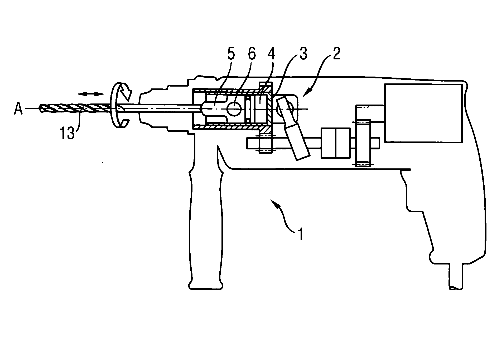
[0025]A rotary-percussion hand-held power tool 1 according to the present invention for driving a working tool 13, which is formed as a combination hammer and is shown in FIG. 1, includes a pneumatic percussion mechanism 2 having a driving cylinder 3 within which a percussion piston 5 reciprocates along a percussion axis A under action of an air spring 4. The percussion piston 5 is pierced by a bore 6 that extends at a right angle to the percussion axis and crosses the same, i.e., is formed as a cross-bore.

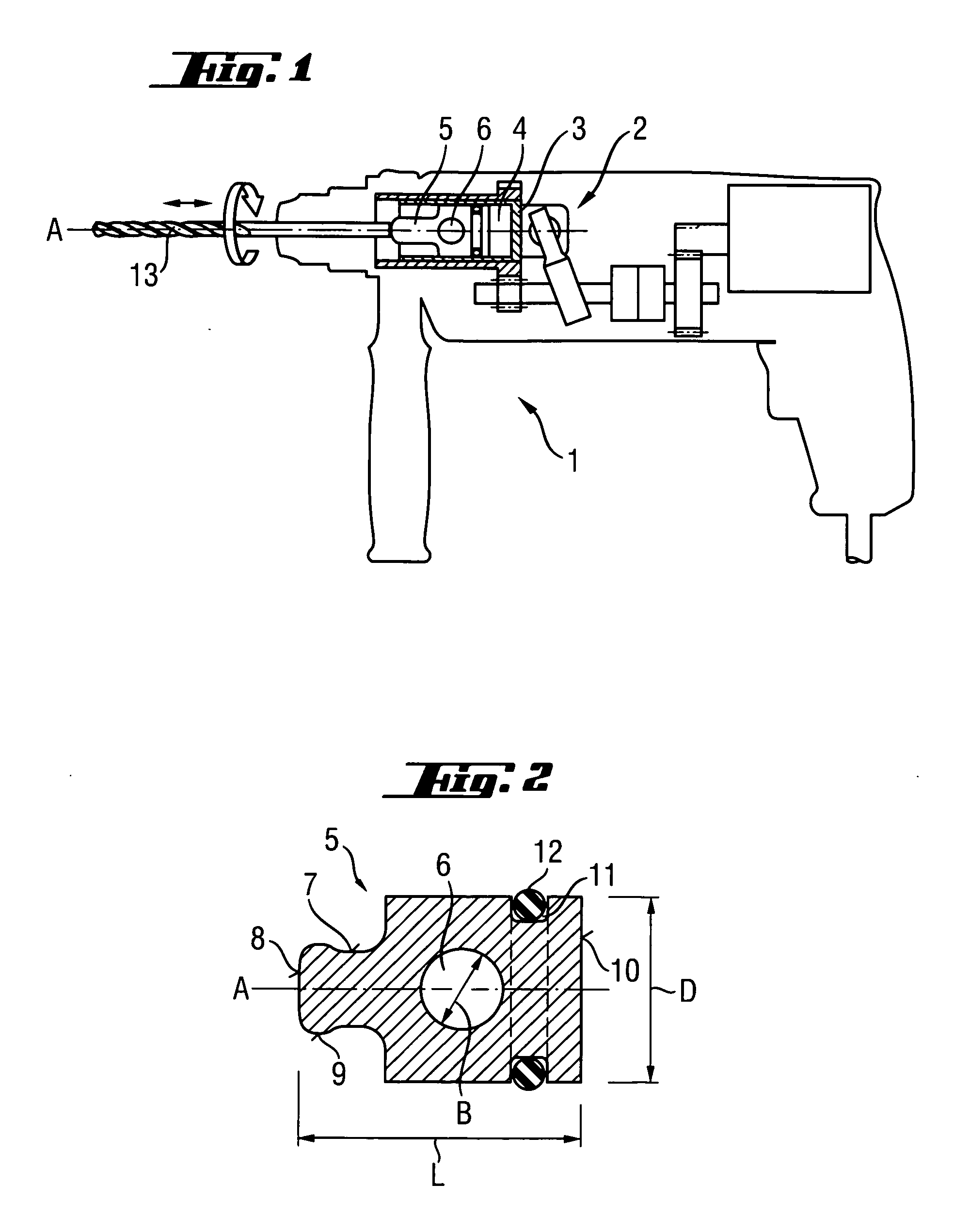
[0026]As shown in FIG. 2, the percussion piston 5 (which is formed rotationally-symmetrical up to the bore 6) and which is formed of steel, has an axial length L that amounts to about 1.5 times of its diameter D. One of the axial end side has a radial reduction 7 with a spherical impact surface 8 and a radial bead 9 formed adjacent to the impact surface 8. The end surface 10 of the percussion piston 5 opposite the impact surface 8 is formed flat. Between the end surface 10 and the...


PUM

PropertyMeasurementUnit
Angleaaaaaaaaaa
Lengthaaaaaaaaaa
Diameteraaaaaaaaaa

Abstract

A hand-held power tool includes a pneumatic percussion mechanism having a percussion piston reciprocating along a percussion axis and having a bore extending at an angle to the percussion axis, and an air spring for displacing the percussion piston.

Description

BACKGROUND OF THE INVENTION[0001]1. Field of the Invention[0002]The present invention relates to a hand-held power tool including a pneumatic percussion mechanism having a percussion piston reciprocating along a percussion axis and an air spring for displacing the percussion piston, and, advantageously, to a hammer drill or a chisel hammer.[0003]2. Description of the Prior Art[0004]Generally, an electromechanically driven percussion mechanism of a hand-held power tool has a percussion piston that reciprocates in a guide tube under action of an air spring. The percussion piston applies blows to a working tool, which is received in a chuck of the power tool, either through an anvil or directly to an end surface of the working tool. To provide for a tilt-free axial displacement of the percussion piston, the axial length of the percussion piston is mostly greater than the guide diameter of the guide tube.[0005]Usually, the percussion piston and, optionally, the anvil are formed of steel...

Claims


Application Information

Patent Timeline
IPC IPC(8): B25D11/04B25D11/06
CPCB25D17/06B25D2211/061B25D2250/391B25D2222/42B25D2217/0023
Inventor ZHONG, JAMESGUO, KEVINBRITZ, ROZY
Owner HILTI AG
Why Eureka
Try Eureka