
Air conditioning control system

a control system and air conditioning technology, applied in the direction of battery/fuel cell control arrangement, vehicle sub-unit features, electrochemical generators, etc., can solve problems such as air conditioning device malfunction

Active Publication Date: 2009-05-21
TOYOTA JIDOSHA KK
View PDF4 Cites 61 Cited by
  • Summary
  • Abstract
  • Description
  • Claims
  • Application Information

AI Technical Summary

Benefits of technology

The present invention is an air conditioning control system that includes a cooling device for fuel cells and an air conditioning control device for vehicles. The system allows for the continuous operation of the main circulation pump when the fuel cell is operating intermittently to prevent an increase in ambient temperature that could lead to malfunctioning of the air conditioning device. The technical effect of this invention is to maintain the ambient temperature of the air compressor at a low level, ensuring the proper functioning of the air conditioning control device.

Problems solved by technology

In such a case, the ambient temperature surrounding the air compressor of the air conditioning device increases, which could lead to malfunctioning of the air conditioning device.

Method used


Image

  • Air conditioning control system
  • Air conditioning control system
  • Air conditioning control system

Examples


Embodiment Construction

[0011]A preferred embodiment of the present invention will be described below with reference to the attached drawings.

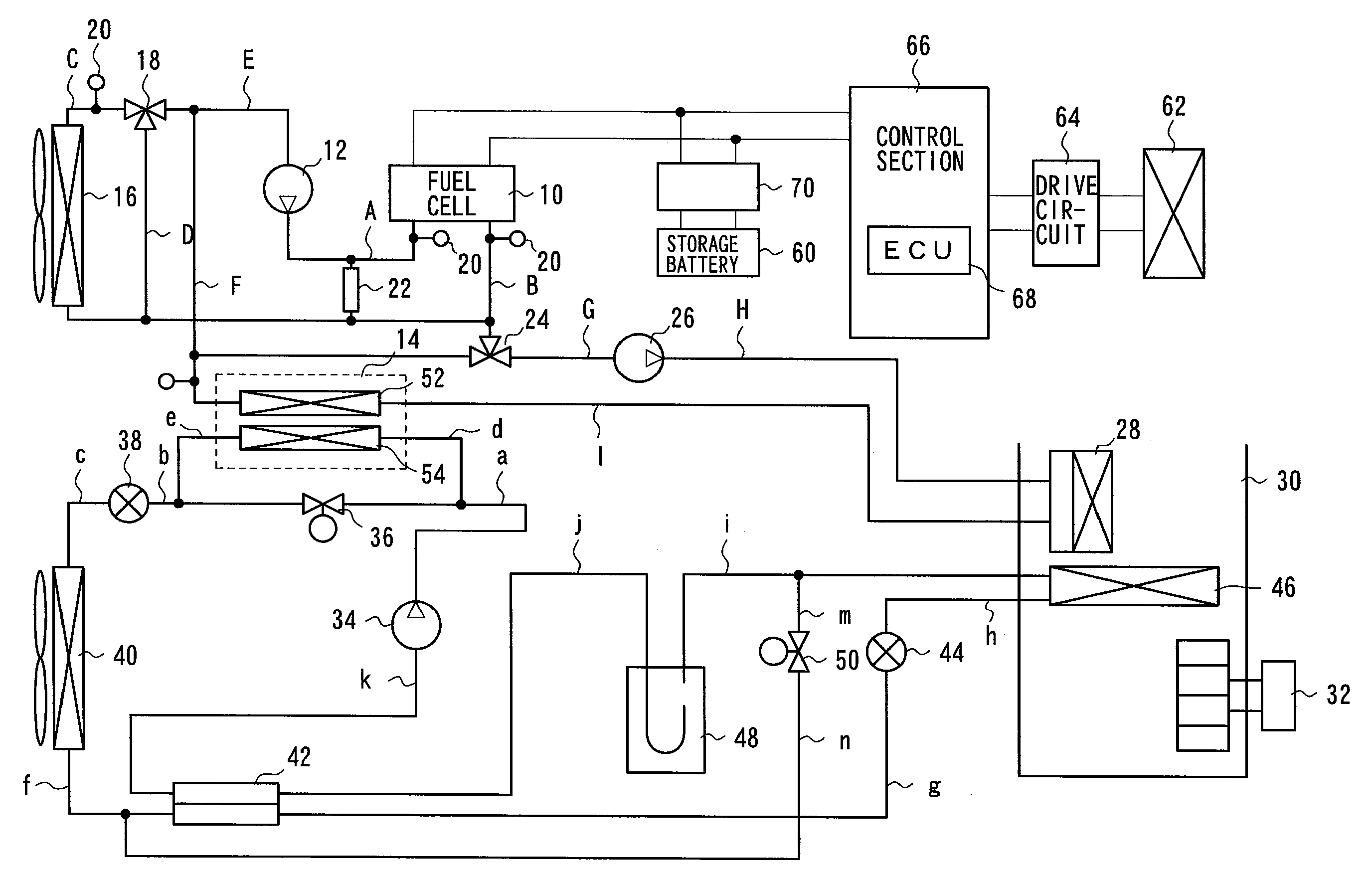
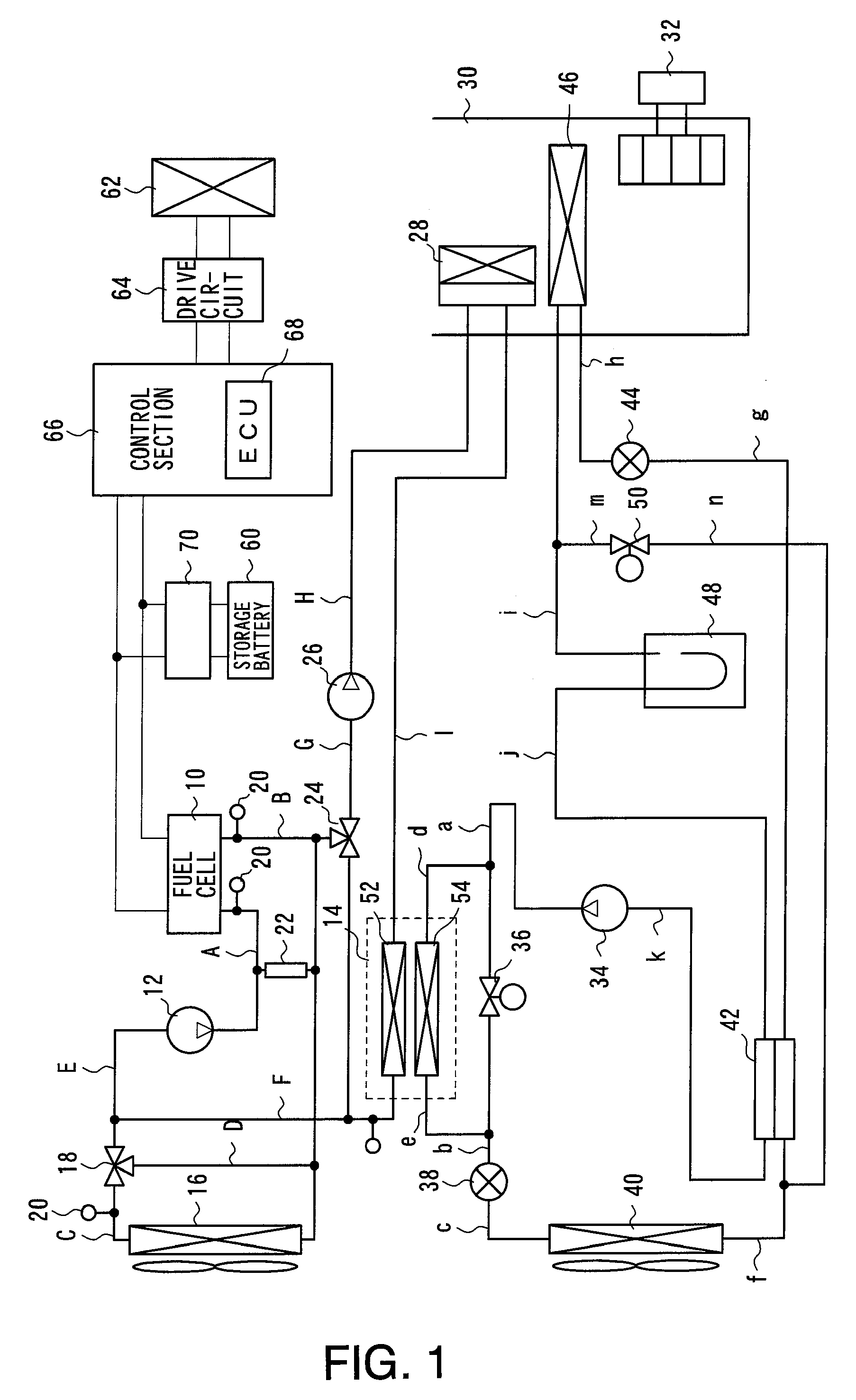
[0012]FIG. 1 is a block diagram showing an arrangement of an air conditioning control system according to the present invention. The air conditioning control system includes a fuel cell system and an air conditioning control device. The fuel cell system and the air conditioning control device shown in FIG. 1 are mounted on a vehicle. The fuel cell system generates electric power used to drive the vehicle. The air conditioning control device regulates the temperature in the interior (passenger compartment, etc.) of the vehicle.

[0013](Fuel Cell System)

[0014]The fuel cell system includes a fuel cell 10 and a cooling device for fuel cell 10.

[0015]Fuel cell 10 is formed by stacking a plurality of single cells, each cell being a power generating unit. Each cell includes an electrolyte, a fuel electrode (anode) and an air electrode (cathode), where two electrodes sandwichin...


PUM

PropertyMeasurementUnit
temperatureaaaaaaaaaa
specific temperatureaaaaaaaaaa
heataaaaaaaaaa

Abstract

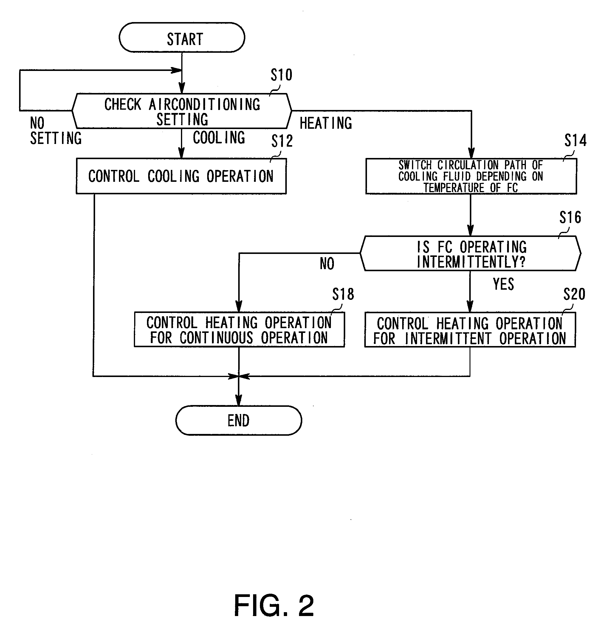
An air conditioning control system having a cooling device for cooling a fuel cell by circulating a liquid coolant through the fuel cell using a main circulation pump while also providing an air conditioning control device for controlling air conditioning in a vehicle interior, wherein heat exchange between the cooling device and the air conditioning control device is possible. When the fuel cell is operated intermittently in the air conditioning control system, the main circulation pump is continuously operated.

Description

BACKGROUND OF INVENTION[0001]1. Field of the Invention[0002]The present invention relates to an air conditioning control system which utilizes a fuel cell.[0003]2. Description of the Related Art[0004]At low temperatures, fuel cells do not generate sufficient power. To attempt to address this problem, there is a technique in which fuel cells are warmed by using the electric power of the fuel cell to heat a liquid coolant when the fuel cell is at a low temperature, such as when activating the fuel cell. To maintain the fuel cell at a specific temperature appropriate for operation, a fuel cell system also includes a cooling device for circulating the coolant to dissipate undesired heat generated in the fuel cell by a radiator.[0005]On the other hand, moving objects which utilize the fuel cell as a power source (e.g., hybrid or electric vehicles or the like) include an air conditioning control device for heating and cooling the passenger compartment or interior of the vehicle. An exampl...

Claims


Application Information

Patent Timeline
Patent Type & Authority Applications(United States)
IPC IPC(8): H01M8/04
CPCB60H1/00385Y02B90/16B60K1/04B60K2001/005B60L1/003B60L11/1887B60L11/1892B60L11/1894H01M8/04029H01M8/04223H01M2250/20H01M2250/405Y02T90/32Y02T90/34Y02E60/50B60H1/143B60L58/33B60L58/34B60L58/40H01M8/04228Y02B90/10Y02T10/70Y02T90/40B60Y2200/91B60Y2200/92B60Y2306/05
Inventor TSUCHIYA, NAOHISAISHIKAWA, TOMOTAKA
Owner TOYOTA JIDOSHA KK
Learn More