
External inline LPG fuel pump

a fuel pump and inline technology, applied in the direction of liquid fuel engines, piston pumps, positive displacement liquid engines, etc., can solve the problems of reducing the efficiency constant wear of the inner surface, and reducing the rotation force of the motor, so as to prolong the life of the fuel pump, prevent the durability of the fuel pump from deteriorating, and reduce the cost of repair and exchang

Inactive Publication Date: 2009-05-14
KOREA INST OF MACHINERY & MATERIALS
View PDF1 Cites 7 Cited by
  • Summary
  • Abstract
  • Description
  • Claims
  • Application Information

AI Technical Summary

Benefits of technology

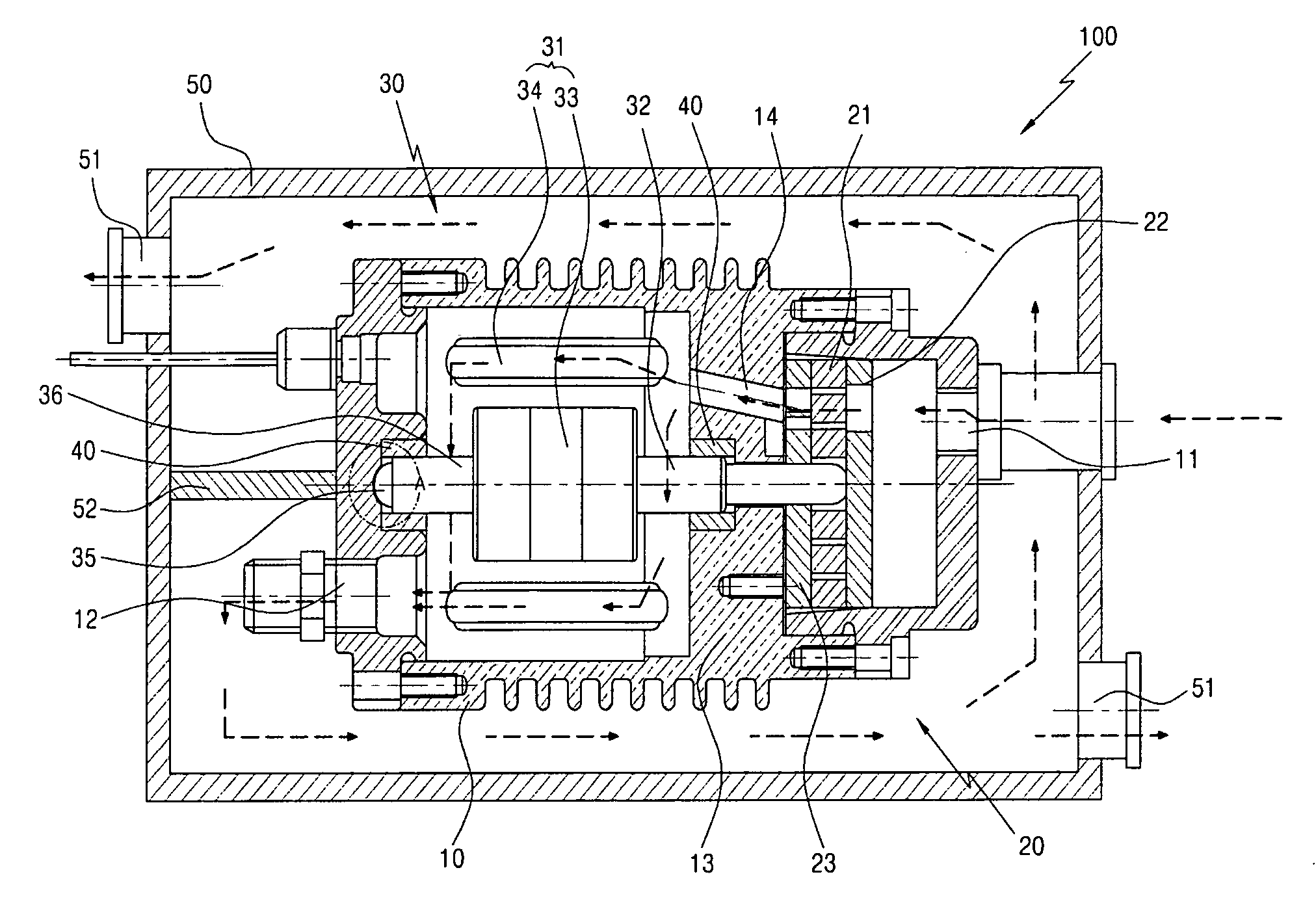
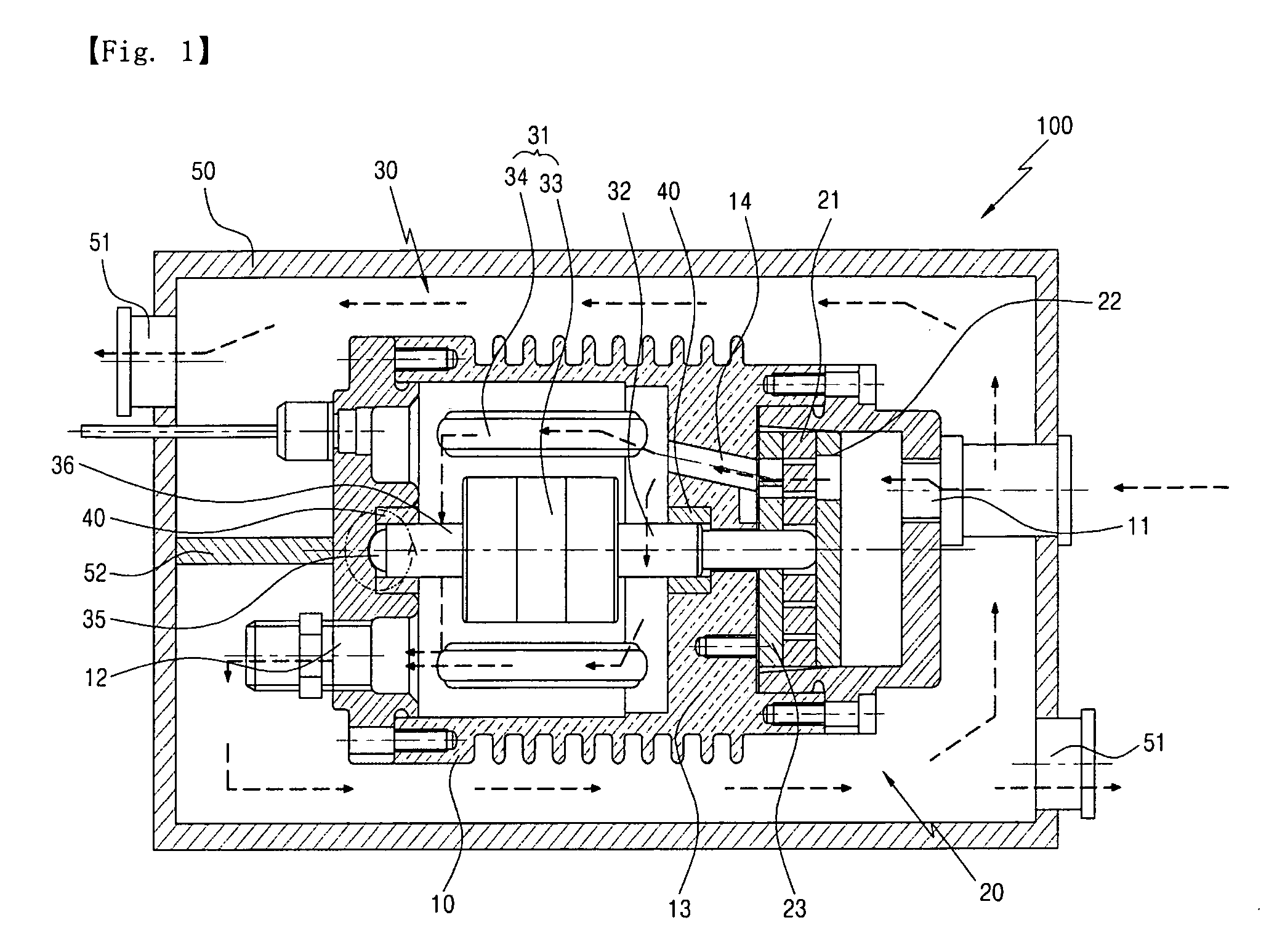
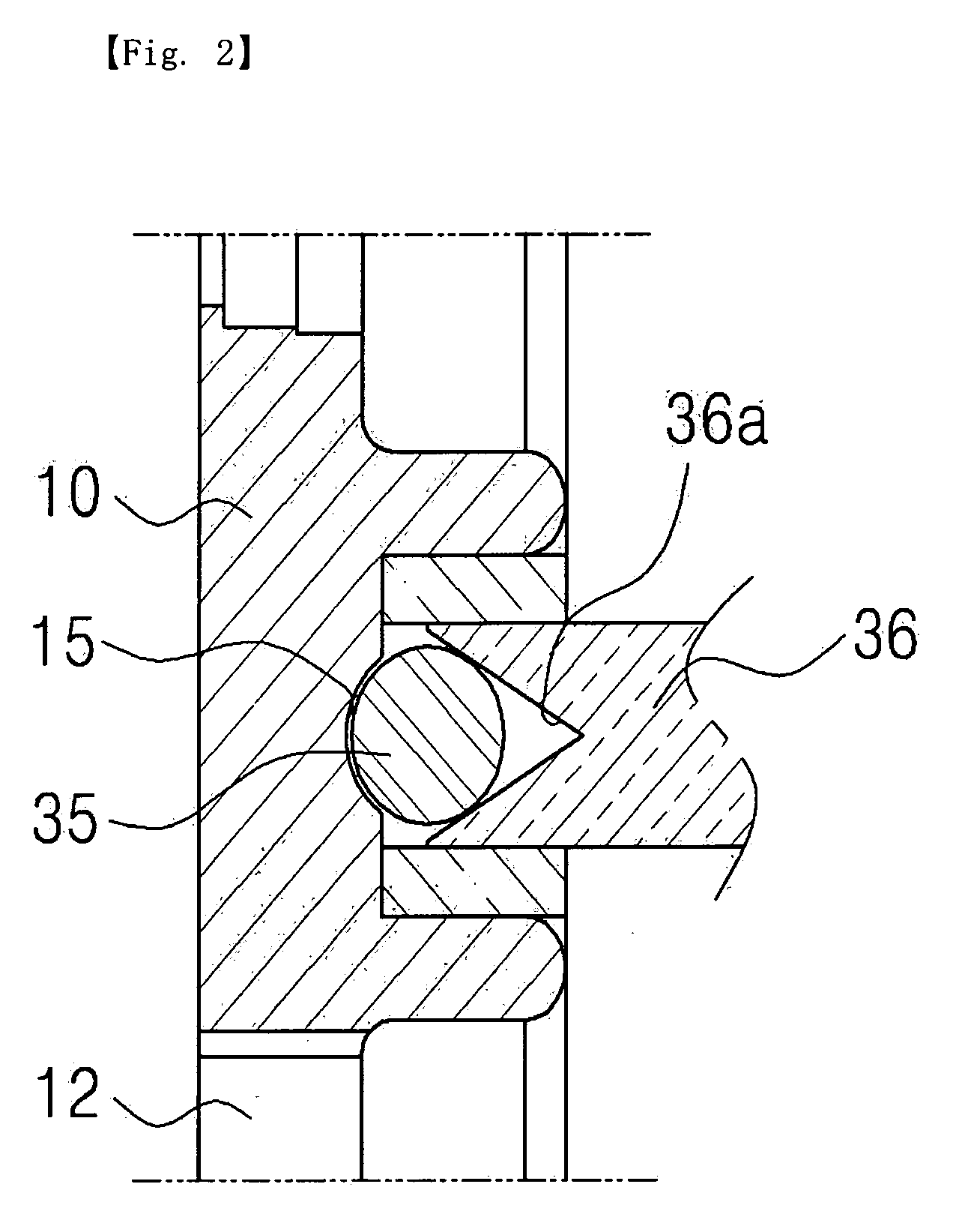
[0015]In accordance with the present invention, in an external inline LPG fuel pump, bushings are installed at first and second shafts of a motor to be fixed inside a housing, a ball is completely coupled to an end of the first shaft to prevent the motor from being shaken due to the bushings, and another ball is inserted into an end of the second shaft to fix the motor. Accordingly, there are the effects of preventing the durability of the fuel pump from deteriorating by wear of a bushing part, a pumping part and an inside of the housing even though an LPG fuel is introduced when the motor is driven, prolonging the life of the fuel pump, and reducing the repair and exchange costs involved with the fuel pump.
[0016]Furthermore, in the external inline LPG fuel pump, a case inside which the housing is positioned is formed and a partition is installed inside the case. Accordingly, there are the effects of cooling the high-temperature LPG fuel as discharged through an outlet of the housing, reducing heat load, and improving the durability of a device receiving the LPG fuel transferred from the fuel pump.
[0017]Furthermore, in the external inline LPG fuel pump, the LPG fuel is introduced from the side of the housing and is inline carried by a carrier. Accordingly, there are the effects of improving an inhale through an inlet and an efficiency of a flow at the inlet.
[0018]Furthermore, in the external inline LPG fuel pump, the carrier comprises a through-aperture formed in its center so as to be coupled to the shaft of the motor, a round protrusion part formed at one surface around the through-aperture, and a number of groove parts having various shapes formed in the circumferential direction of the round protrusion part around the through-aperture. Accordingly, there are the effects of maintaining the equal pressure at both sides of the carrier when the fuel is introduced through the groove parts, preventing the carrier from being pushed to one side by the pressure of the fuel introduced into the fuel pump, and preventing noise and damage caused by friction when the carrier is rotated.

Problems solved by technology

However, when the built-in pump is out of order, the fuel tank has to be replaced to fix the built-in pump.
However, the bearing is continuously worn against an inner surface of the fuel pump by the rotation of the shaft.
Therefore, when the fuel pump is used for a long time, the bearing is seriously worn away and a rotation force of the motor decreases, thereby lowering the efficiency of the fuel pump.
Moreover, when the bearing is worn away, it needs to be repaired or replaced and increases the maintenance cost, thereby decreasing the productivity and the demand of the external fuel pump.
Therefore, as the rotary vane continuously rotates while contacting with the case, a frictional force increases, thereby causing noise and damage.

Method used


Image

  • External inline LPG fuel pump
  • External inline LPG fuel pump
  • External inline LPG fuel pump

Examples


first embodiment

[0037]As illustrated in FIG. 1, an external LPG fuel pump 100 according to the present invention comprises a housing 10, a pumping part 20, a motor part 30 and a case 50.

[0038]The housing 10 comprises an inlet 11 and an outlet 12 formed at its opposite sides, to introduce and discharge an LPG fuel. The inlet 11 of the housing 10 is connected to a fuel tank (not shown) and the outlet 12 of the housing 10 is connected to a fuel injector (not shown) of an engine.

[0039]That is, the fuel pump 100 according to this embodiment is an external inline fuel pump to be installed in a fuel line connecting the fuel tank to the fuel injector.

[0040]Inside the housing 10, the pumping part 20 is positioned in a space formed at the side towards the inlet 11, and the motor part 30 is positioned in another space at the side towards the outlet 12. A guide layer 13 is formed to divide the inner space of the housing 10 into the side of the pumping part 20 and the side of the motor part 30. A fuel channel 1...

second embodiment

[0063]As illustrated in FIGS. 4 and 5, a housing 10 comprises an inlet 11 and an outlet 12. The inlet 11 is formed at one end side of the housing 10, to introduce an LPG fuel. The outlet 12 is formed at another end of the housing 10. The inlet 11 of the housing 10 is connected to a fuel tank (not shown), and the outlet 12 of the housing 10 is connected to a fuel injection (not shown) of an engine.

[0064]With reference to FIGS. 4 and 6, a pumping part 20 is connected to a first shaft 32 of a motor part 30. The pumping part 20 comprises a carrier 21, a roller 24, a first plate 22, and a second plate 23. The carrier 21 rotated by the first shaft 32 introduces and carries the LPG fuel from the inlet 11 of the housing 10 into the housing 10. The roller 24 is formed to surround the outer circumferential surface of the carrier 21. The first plate 22 is positioned at one side of the carrier 21 and includes an intake groove 25 formed in a fan-shape at a lower surface spanned over both lateral...

third embodiment

[0066]As illustrated in FIG. 7, a ball 35 is combined integrally with a center part of a housing 10 in the side of an outlet 12 and contacts with an end of a second shaft 36. Therefore, the second shaft 36 is smoothly rotated by the ball 35. The ball 35 is attached to the housing 10 when the housing 10 is manufactured.

[0067]The other constitution of the external LPG fuel pump according to the third embodiment is the same as that of the external LPG fuel pump according to the first embodiment.


PUM


Abstract

There is provided an external inline LPG fuel pump, and more particularly, an external inline LPG fuel pump; in which bushings are installed at first and second shafts of a motor to be fixed inside a housing, a ball is completely coupled to an end of the first shaft to prevent the motor from being shaken due to the bushings, and another ball is inserted into an end of the second shaft to fix the motor, thereby preventing the durability of the fuel pump from deteriorating by wear of a bushing part, a pumping part and an inside of the housing even though an LPG fuel is introduced when the motor is driven, prolonging the life of the fuel pump and reducing the repair and exchange costs involved with the fuel pump; in which a case inside which the housing is positioned is formed and a partition is installed inside the case, thereby cooling the high-temperature LPG fuel discharged through an outlet of the housing to reduce heat load and improving the durability of a device receiving the LPG fuel transferred from the fuel pump.

Description

CROSS-REFERENCE TO RELATED APPLICATIONS[0001]This application claims the benefit of Korean Patent Application No. 10-2007-0114892 filed Nov. 12, 2007, Korean Patent Application No. 10-2007-0132739 filed Dec. 17, 2007, Korean Patent Application No. 10-2007-0132740 filed Dec. 17, 2007, and Korean Patent Application No. 10-2008-0020121 filed Mar. 4, 2008, the disclosures of each which are hereby incorporated herein by reference in their entireties.TECHNICAL FIELD[0002]The present invention relates to an external inline LPG fuel pump, and more particularly, an external inline LPG fuel pump; in which bushings are installed at first and second shafts of a motor to be fixed inside a housing, a ball is completely coupled to an end of the first shaft to prevent the motor from being shaken due to the bushings, and another ball is inserted into an end of the second shaft to fix the motor, thereby preventing the durability of the fuel pump from deteriorating by wear of a bushing part, a pumping...

Claims


Application Information

Patent Timeline
Patent Type & Authority Applications(United States)
IPC IPC(8): F02M37/08
CPCF02M37/08F04C2/10F04C2/344F04C15/0096F04C2210/10F02M21/0245F04C2240/50F04C2210/1061F02M21/0212Y02T10/32Y02T10/30
Inventor KIM, CHANG UPPARK, CHUL WOONGCHOI, KYO NAMKANG, KERN YONGOH, SEUNG MOOKLEE, AN SUNG
Owner KOREA INST OF MACHINERY & MATERIALS
Learn More