
drive unit

A technology of driving device and control device, which is applied in the direction of power device, electrical device, control drive, etc., can solve the problem of increased energy consumption of the braking mechanism, and achieve the effects of simplifying control, improving responsiveness, and suppressing slippage

Active Publication Date: 2019-06-21
HONDA MOTOR CO LTD
View PDF7 Cites 0 Cited by
  • Summary
  • Abstract
  • Description
  • Claims
  • Application Information

AI Technical Summary

Problems solved by technology

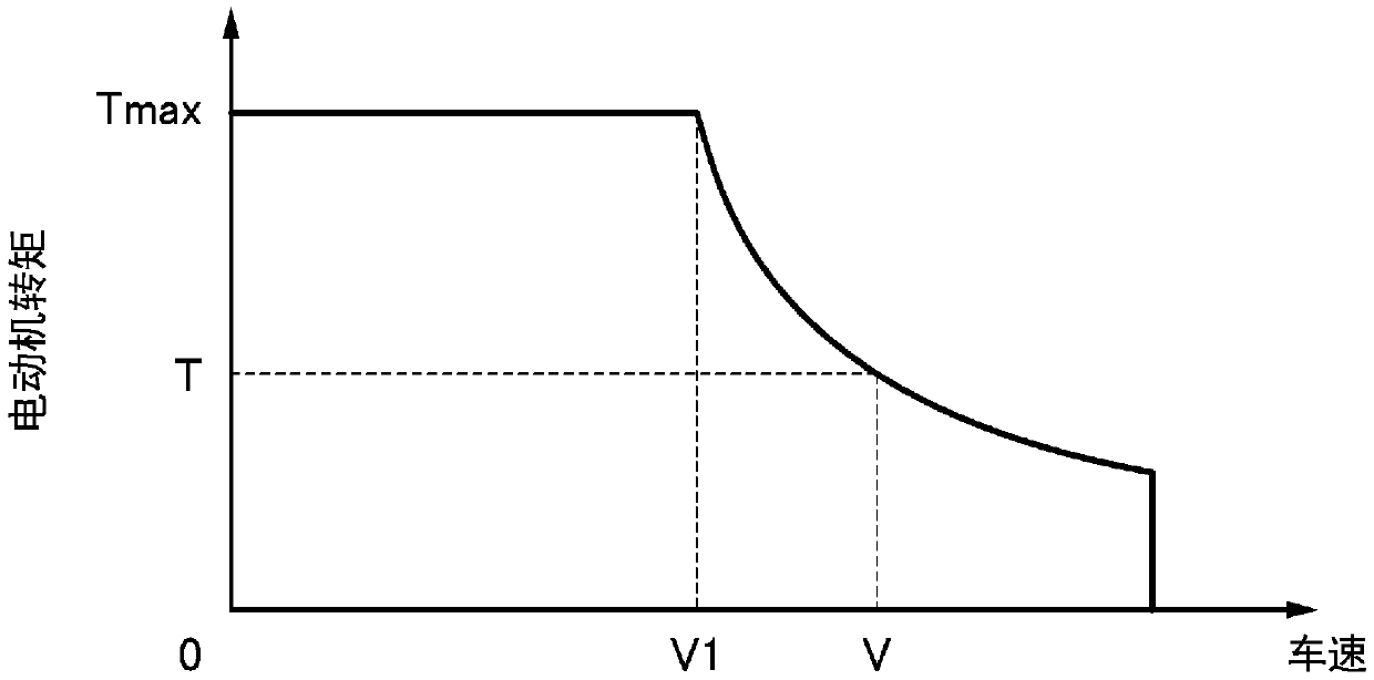
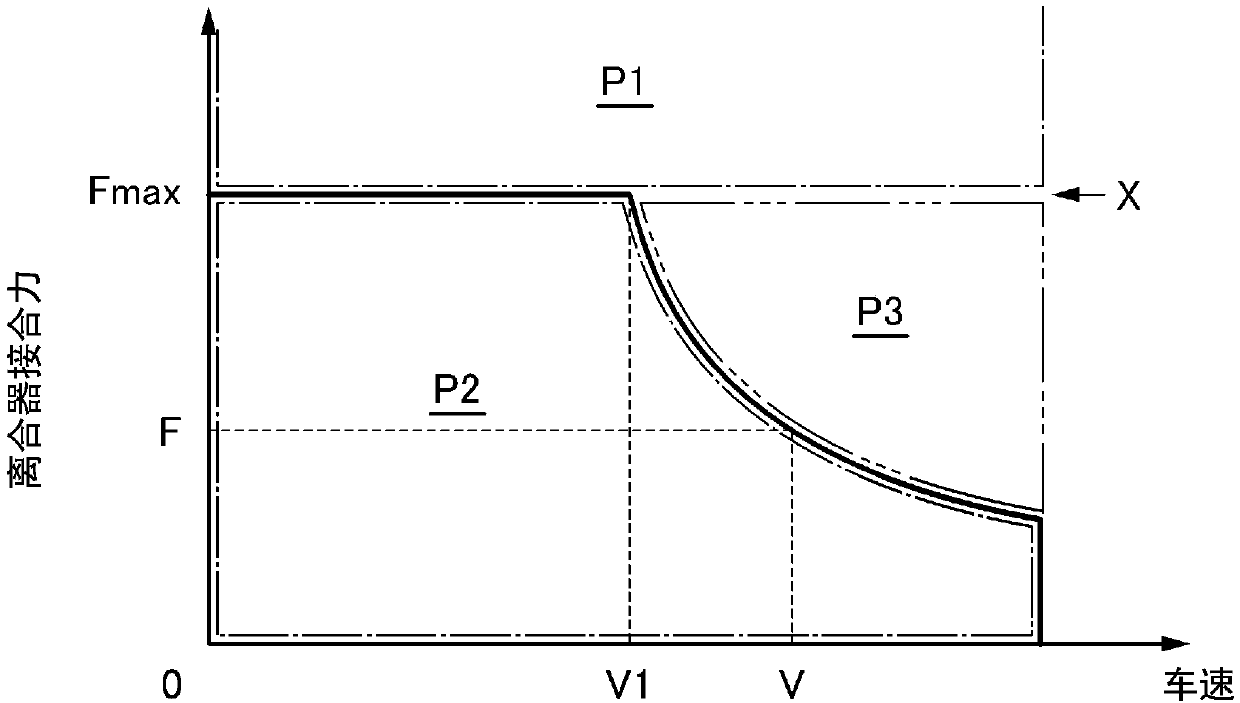
In addition, when using an electric motor, if the power transmission mechanism is always controlled to an engagement force exceeding the necessary brake engagement force regardless of the vehicle speed, the energy consumption of the brake mechanism will increase.

Method used


Image

  • drive unit
  • drive unit
  • drive unit

Examples


no. 1 approach

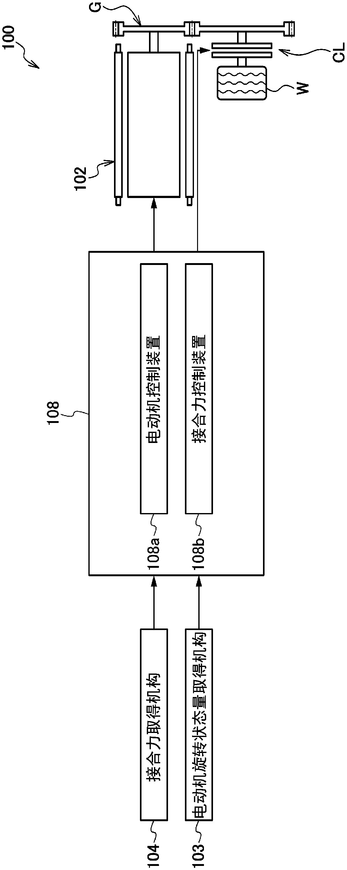
[0091] Such as figure 1 As shown, the driving device 100 of the first embodiment has a motor 102 and a clutch CL provided on a power transmission path between the motor 102 and the wheels W as a power transmission mechanism. The clutch CL is a hydraulic clutch, and is configured to be able to change the engagement force to change the power transmission capacity of the power transmission path.

[0092] The control device 108 of the driving device 100 includes a motor control device 108 a that controls the torque generated by the electric motor 102 and an engagement force control device 108 b that controls the engagement force of the clutch CL.

[0093] The engagement force control device 108b that controls the engagement force of the clutch CL can adjust the engagement force of the clutch CL by adjusting the rotation speed of the oil pump or adjusting the hydraulic pressure of the hydraulic circuit.

[0094] A motor control device 108 a that controls the torque generated by th...

no. 2 approach

[0111] The drive device 1 of the second embodiment uses an electric motor as a drive source for driving an axle, and is used, for example, in image 3 The drive system of the vehicle is shown. In the following description, a case where the driving device is used for driving the rear wheels will be described as an example, but the driving device may also be used for driving the front wheels.

[0112] image 3 The illustrated vehicle 3 is a hybrid vehicle having a driving device 6 (hereinafter referred to as a front-wheel drive device) in which an internal combustion engine 4 and an electric motor 5 are connected in series at the front of the vehicle, and the power of the front-wheel drive device 6 is transmitted via a transmission device. 7 is transmitted to the front wheels Wf, and on the other hand, the power of the driving device 1 (hereinafter referred to as the rear wheel driving device) provided in the rear of the vehicle separately from the front wheel driving device 6 ...


PUM


Abstract

A vehicle drive device (100) includes an electric motor (102) connected to the wheels (W) so as to be able to transmit power, and a clutch (CL) provided on a power transmission path between the electric motor (102) and the wheels (W), And the power transmission capacity of the power transmission path can be changed by controlling the engagement force; a motor control device (108a), which controls the power generated by the electric motor (102); an engagement force control device (108b), which controls the engagement force of the clutch (CL); An engagement force acquisition mechanism (104) acquires the engagement force of the clutch (CL). When a motor control device (108b) receives a request for power generation in a state where the motor (102) is not generating power, the motor is based on the current engagement force of the clutch (CL) and the current rotation state amount for the motor (102) The engagement force of the clutch (CL) required to transmit the maximum generated power of the (102), that is, the necessary engagement force, controls the permission and / or prohibition of the power generation of the electric motor (102).

Description

technical field [0001] The present invention relates to a drive device including an electric motor and a power transmission mechanism capable of changing the power transmission capacity of a power transmission path between the electric motor and wheels. Background technique [0002] Conventionally, a drive device for a vehicle including an electric motor and a power transmission mechanism capable of changing the power transmission capacity of a power transmission path between the electric motor and wheels is known. For example, the vehicle drive device described in Patent Document 1 describes that the engagement force of the hydraulic brake is controlled based on the viscosity or the like in view of the change in the engagement force required of the hydraulic brake as a power transmission mechanism due to the viscosity or the like of oil. [0003] In addition, it is described that during regeneration, a hydraulic brake is strongly engaged and an electric motor is regenerativ...

Claims


Application Information

Patent Timeline
Patent Type & Authority Patents(China)
IPC IPC(8): B60K7/00B60K17/04B60K17/354B60K17/356B60L7/14B60L15/20B60L50/50B60L50/16
CPCB60K17/356B60K7/0007B60K17/354B60K2007/0053B60L2240/421B60L2240/423B60L2240/507B60L7/14B60L15/2036B60L15/2054B60L2220/46B60L2240/486B60L2260/28B60L50/16B60K17/046B60L15/2009B60L50/60Y02T10/72Y02T10/64Y02T10/70Y02T10/7072B60K6/44B60K6/52B60W10/02B60W10/08B60W20/14B60K2006/4825
Inventor 小西庆明阪口雄亮
Owner HONDA MOTOR CO LTD
Learn More