Low noise tire
A technology for pneumatic tires and treads, applied in tire parts, wheels, transportation and packaging, etc., can solve the problems of decreased durability and commercial value, easy problems with mufflers, and low bonding efficiency. The effect of preventing the decline in the commercial value of tires and preventing the deterioration of durability
- Summary
- Abstract
- Description
- Claims
- Application Information
AI Technical Summary
Problems solved by technology
Method used
Image
Examples
no. 1 example
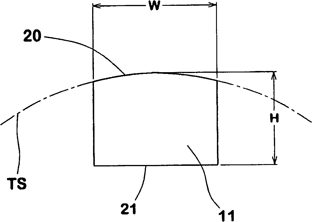
[0044] figure 2 A first embodiment of a sound absorbing body material is shown, wherein the sound absorbing body is in an unstressed state not yet bonded, and the surface 20 to be bonded (hereinafter referred to as the joint surface 20) is convexly curved to resemble the inner surface The curvature of TS so as to closely fit the inner surface TS.
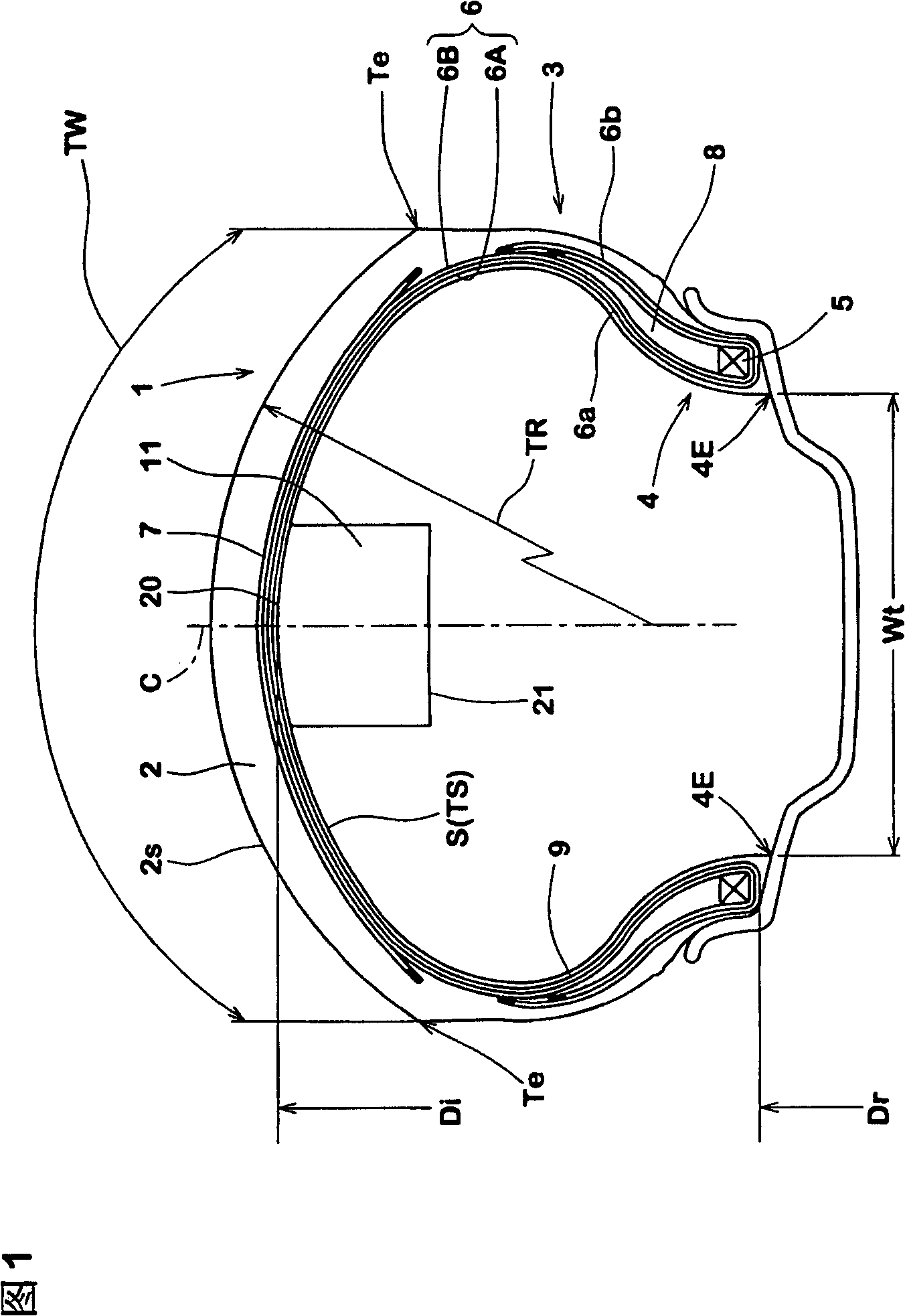
[0045] If the maximum width W of the sound absorber is close to the width between the toes 4E, it will be difficult to insert the sound absorber material into the inner cavity of the tire and the bonding work efficiency will become low. Therefore, the width W is preferably set to be not more than 80% of the axial width Wt between the toes 4E.
no. 2 example
[0047] If the joint surface 20 has an uncurved portion or a flat portion, the width of the flat portion must not be greater than 30% of the tread width along the tread surface 2s. If it is more than 30%, the above-mentioned problems such as wrinkles are prone to occur.
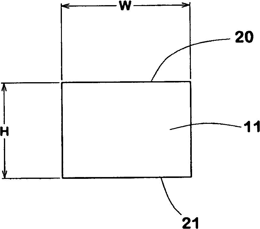
[0048] Such as image 3 As shown, if the joint surface 20 is flat as a whole, the width W of the muffler material must not be greater than 30% of the tread width TW. In this case, since the width W is relatively narrow, its thickness H is not less than 5.0 mm, preferably at least 0.6 times the width W, in order to obtain a sufficient noise reduction effect.
no. 3 example
[0050] If the joint surface 20 of the muffler material used is not curved or flat, and the width W is greater than 30% of TW, then as Figure 4 As shown, each axial edge 11e must be provided with regularly spaced V-shaped grooves 24 along its length.
[0051] In spite of the grooves, if the width W exceeds 90% of TW, it is also difficult to completely prevent wrinkles and edge irregularities because the bonding work becomes difficult. Therefore, the width W is preferably not greater than 90%, more preferably less than 75%, of the tread width TW.
[0052] The groove 24 extends from the side 11e of the muffler material to its centerline N while reducing the gap (k) between the opposite edges 24e of the groove and at an axial distance Ye from the side 11e in front of the centerline N termination. Thus, the muffler body 11 has a continuous central portion Yc between the axially inner ends of the grooves 24 and side portions Ye separated by the grooves 24 .
[0053] If the width...
PUM
 Abstract
Description
Claims
Application Information
 - R&D
- Intellectual Property
- Life Sciences
- Materials
- Tech Scout
- Unparalleled Data Quality
- Higher Quality Content
- 60% Fewer Hallucinations
Browse by: Latest US Patents, China's latest patents, Technical Efficacy Thesaurus, Application Domain, Technology Topic, Popular Technical Reports.
© 2025 PatSnap. All rights reserved.Legal|Privacy policy|Modern Slavery Act Transparency Statement|Sitemap|About US| Contact US: help@patsnap.com


