
Combustion Apparatus

a technology of combustion apparatus and air bubbles, which is applied in the direction of combustion types, lighting and heating apparatus, greenhouse gas reduction, etc., can solve the problems of deterioration of durability and generation of air bubbles, and achieve the effect of reducing the amount of air bubbles, preventing durability from deterioration, and facilitating flow

Active Publication Date: 2020-08-27
RINNAI CORP
View PDF0 Cites 0 Cited by
  • Summary
  • Abstract
  • Description
  • Claims
  • Application Information

AI Technical Summary

Benefits of technology

The invention aims to prevent air bubbles from accumulating in the fourth jacket part, which can lead to deterioration in durability. This is achieved by creating a difference in height between the hot water outlet port and the tip of the fourth jacket part, which accelerates natural convection and helps to remove air bubbles from the fourth jacket part. Additionally, the upper surface of the fourth jacket part is formed in an inclined surface that facilitates the flow of air bubbles towards the outlet-side jacket part, further reducing the likelihood of air bubbles staying in the fourth jacket part.

Problems solved by technology

By the way, there are cases where a part of the heat absorbing tubes is locally overheated (boiled) and, consequently, gives rise to generation of air bubbles in the heat absorbing tubes of the heat exchanger.
Then, since that portion of the fourth jacket part in which the air bubbles get accumulated can no longer be cooled by water, the temperature therein will increase and consequently the scales are likely to get accumulated, resulting in deterioration of the durability.

Method used


Image

  • Combustion Apparatus
  • Combustion Apparatus
  • Combustion Apparatus

Examples


Embodiment Construction

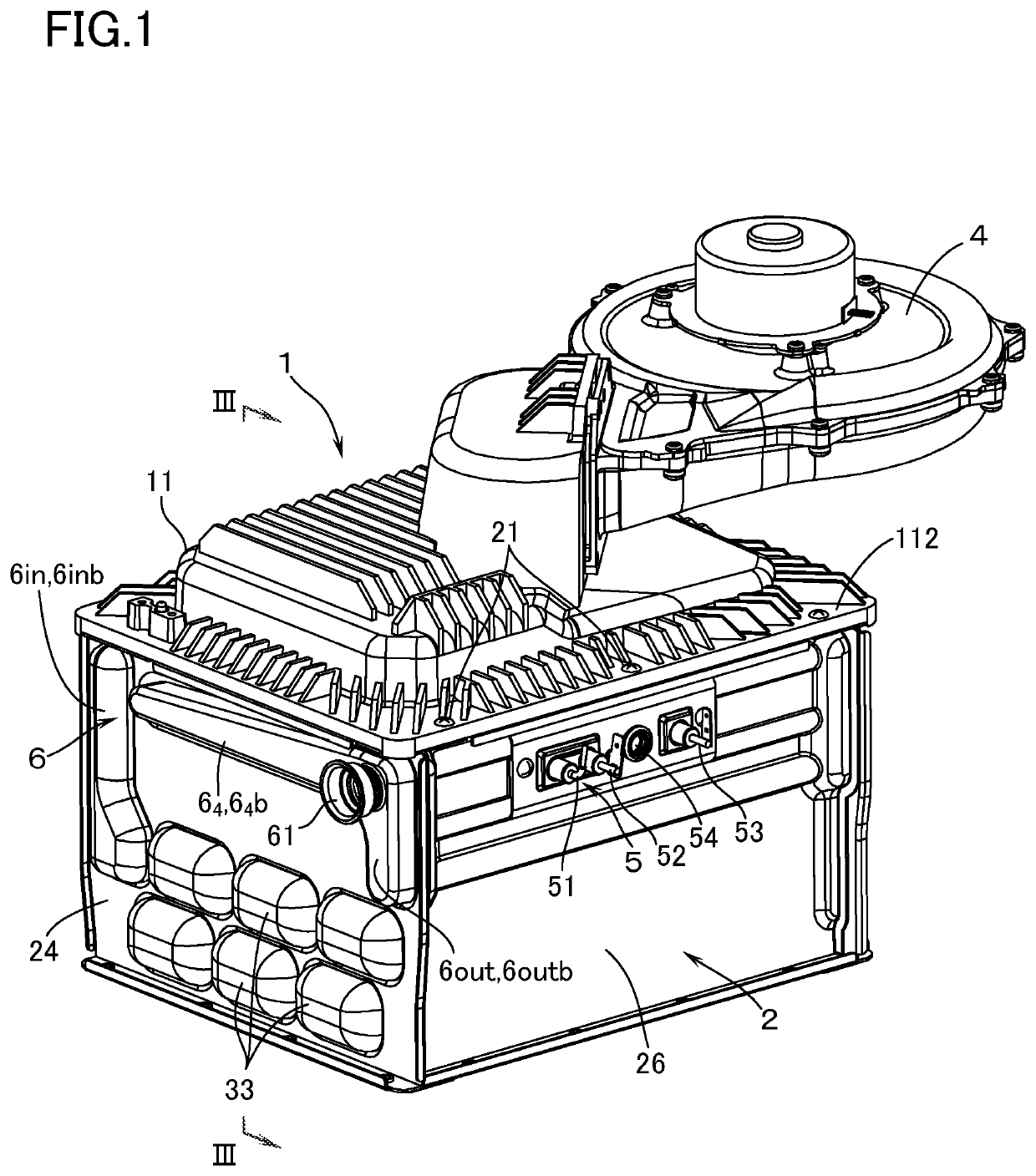
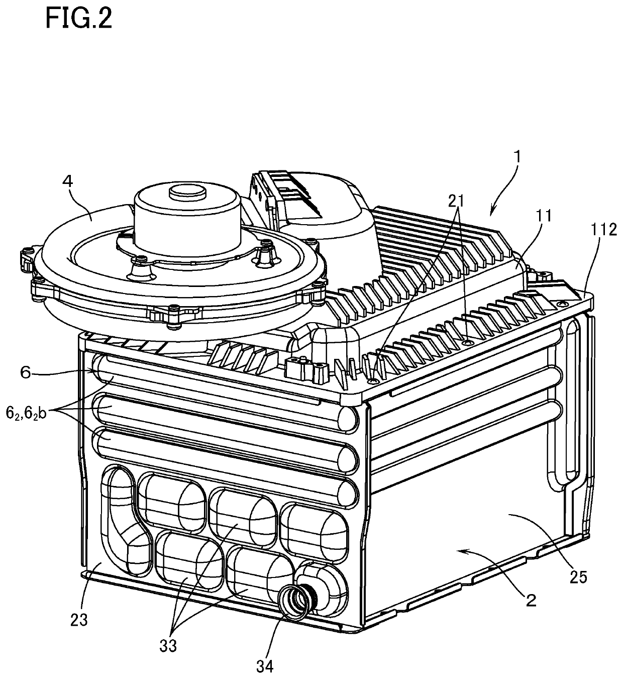
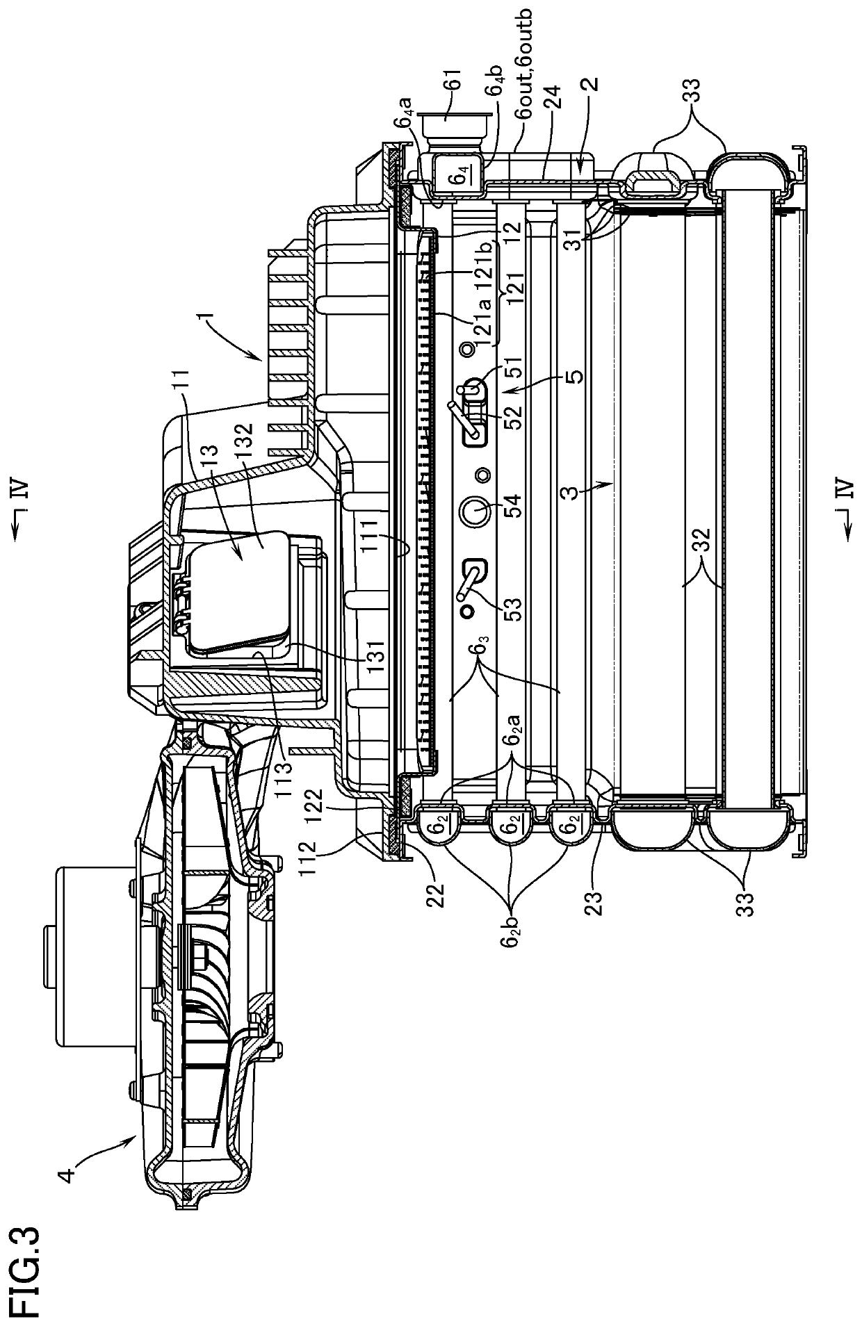
[0016]With reference to FIG. 1 to FIG. 4, a combustion apparatus according to an embodiment of this invention is provided with: a burner 1 made up of a burner body 11 which is supplied inside thereof with air-fuel mixture (mixture gas of fuel gas and primary air), and a sheet-metal combustion plate 12 which covers a downward open surface 111 of the burner body 11 so that the air-fuel mixture is ejected downward from an air-fuel mixture ejection part 121 disposed in the combustion plate 12; and a combustion box 2 which is located on the lower side of the burner 1 and which encloses the combustion space for the air-fuel mixture to be ejected from the burner 1. In addition, in a lower part inside the combustion box 2, there is housed a heat exchanger 3 for supplying hot water. Further, on an upper end part of the combustion box 2, there is disposed a connection flange part 22 which is coupled, with machine screws 21, to a body flange part 112 which encloses an open surface of the burne...


PUM


Abstract

In a combustion apparatus including a burner, a combustion box on a lower side of the burner and enclosing a heat exchanger, and a water jacket in the combustion box and connected to a downstream side of the heat exchanger, the water jacket is arranged to connect together an inlet jacket part disposed in one lateral-side side plate of the combustion box, and an outlet jacket part having a hot water outlet port through jacket parts disposed in the other side plates of the combustion box. An extension jacket part is disposed so as to be elongated from an upper part of the outlet jacket part toward the inlet jacket part and formed such that a sectional center of a tip is positioned below a sectional center of the hot water outlet port.

Description

TECHNICAL FIELD[0001]The present invention relates to a combustion apparatus provided with: a burner for ejecting air-fuel mixture downward; a combustion box which is disposed under the burner in order to enclose the combustion space of the air-fuel mixture to be ejected from the burner; and a heat exchanger disposed in a lower part inside the combustion box.BACKGROUND ART[0002]Conventionally, as this kind of combustion apparatus, there is known an apparatus in Patent Document 1 in which, in order to improve the heat resistivity of the combustion box, a water jacket as a cooling means for cooling the combustion box is disposed in that portion of the combustion box which lies between the burner and the heat exchanger. The water jacket is constituted by: a laterally elongated first jacket part disposed on one of the front-side and the rear-side side plates of the combustion box; a laterally elongated third jacket part disposed on the other of the front-side and the rear-side side plat...

Claims


Application Information

Patent Timeline
Patent Type & Authority Applications(United States)
IPC IPC(8): F23D14/78F23M5/08
CPCF23M5/08F23D14/78F24H1/14F24H9/00Y02E20/30F23D14/36F23M11/042F24H9/0005
Inventor ONO, TAKAHIRO
Owner RINNAI CORP
Learn More