
Imaging device performing color image data processing

a color image and data processing technology, applied in the field of image data processing devices, can solve the problems of image line crawling (line-shaped or grid-like noise), fixed pattern noise, and difference in the sensitivity of each pixel, and achieve the effect of reducing line crawling

Inactive Publication Date: 2009-05-14
NIKON CORP
View PDF15 Cites 7 Cited by
  • Summary
  • Abstract
  • Description
  • Claims
  • Application Information

AI Technical Summary

Benefits of technology

The present invention provides a method for reducing line crawling without image smoothing processing in an imaging device using a color image sensor. The method involves estimating difference in a signal level exerted on a pixel signal of a pixel in a color image sensor, and correcting the pixel signal based on the estimated difference. This helps to improve image quality and reduce blurring and smoothing processing. The method can be implemented in imaging devices that use a color image sensor with pixels of at least two types of color components.

Problems solved by technology

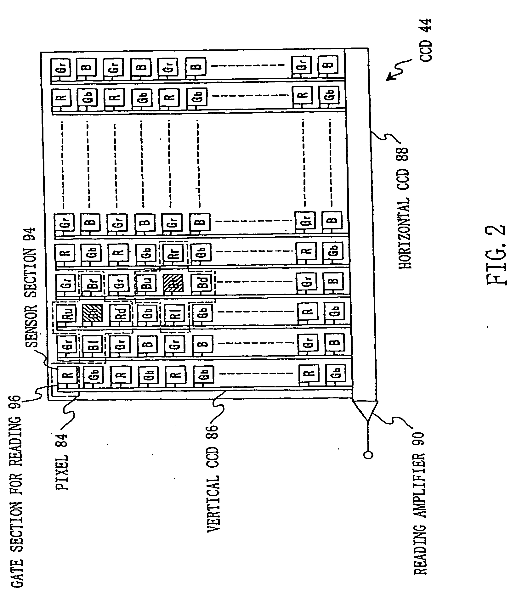
When shooting by a video camera or an electronic camera, there are cases where line crawling (line-shaped or grid-like noise) occurs in an image.
A cause of the occurrence of the line crawling is fixed pattern noise, such as difference in the sensitivity of each pixel, difference in the output level of each vertical transfer line and the like in a color image sensor.
It is difficult, however, to effectively subject image data to the sharpness enhancing processing after being smoothed.
Therefore, it is difficult to obtain a fine image with sharpness from original image data with the line crawling.

Method used


Image

  • Imaging device performing color image data processing
  • Imaging device performing color image data processing
  • Imaging device performing color image data processing

Examples


Embodiment Construction

[0025]An embodiment of the present invention will be hereinafter described with reference to the drawings.

Configuration of this Embodiment

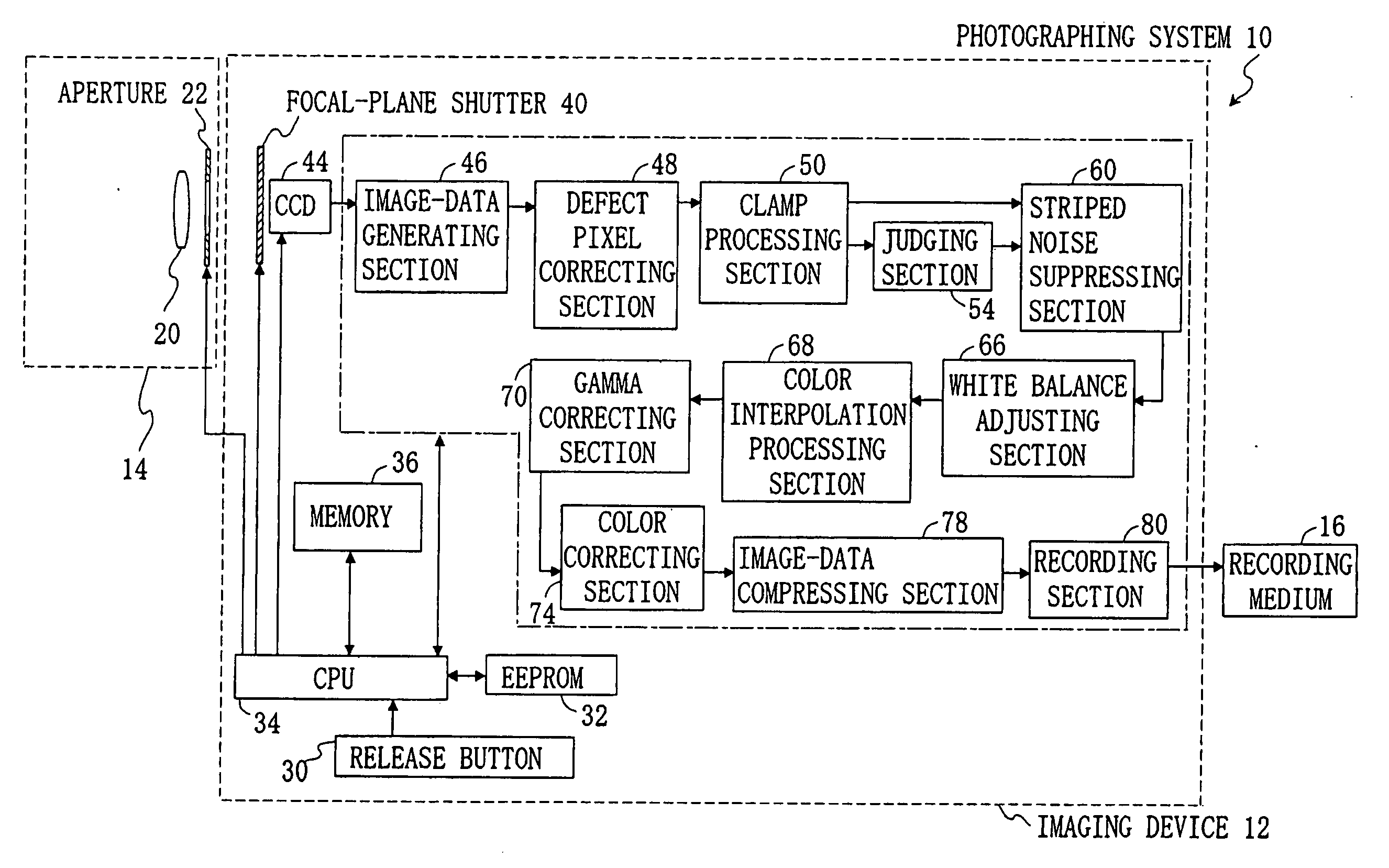
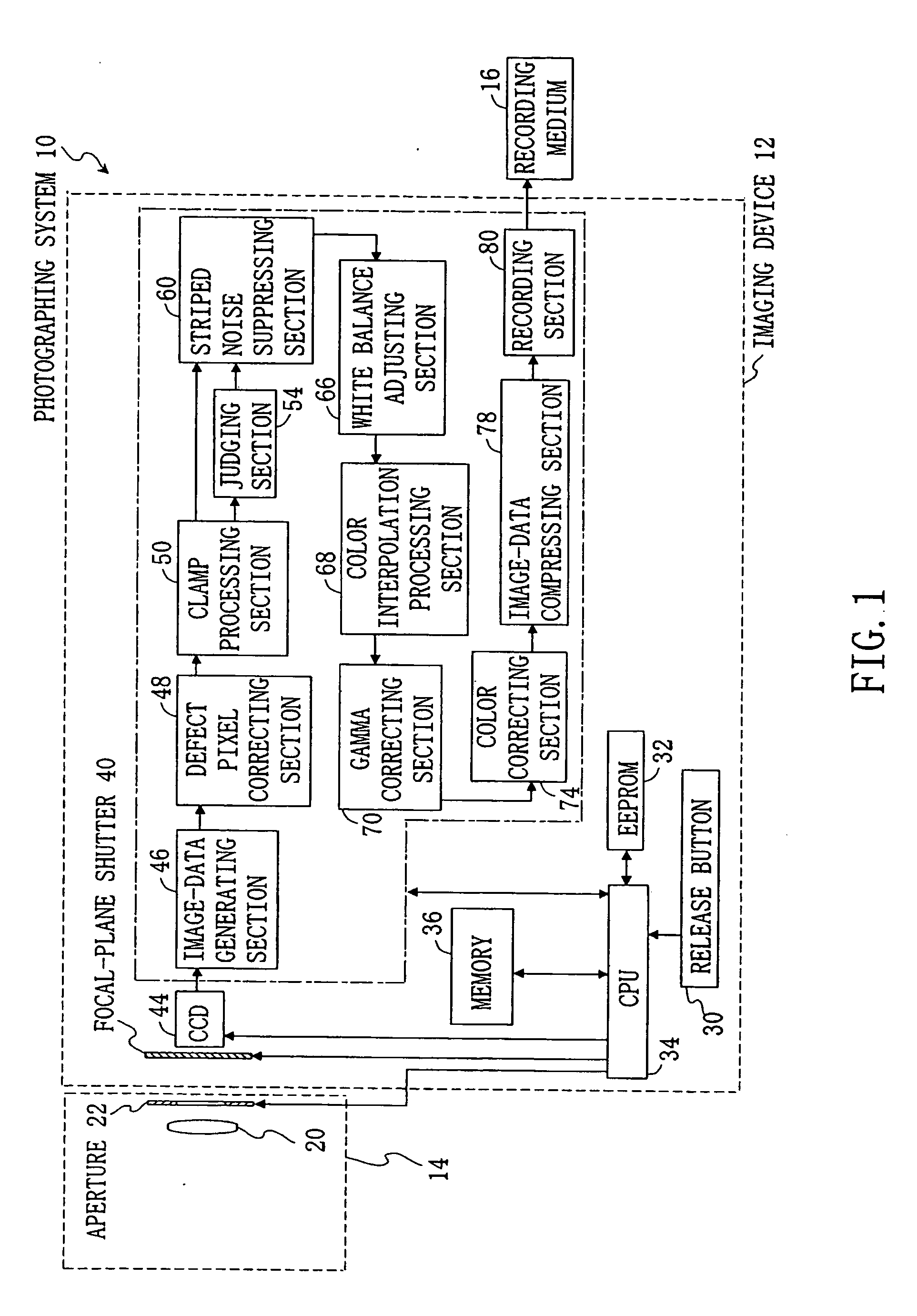
[0026]FIG. 1 shows a block diagram of a photographing system in which an imaging device according to the present invention is installed. Referring to FIG. 1, a photographing system 10 includes an imaging device 12 according to the present invention, a phototaking lens 14 attached to the imaging device 12, and a recording medium 16 connected to the imaging device 12. The phototaking lens 14 includes a lens group 20 and an aperture 22. In this embodiment, by way of example, the imaging device 12 composes an electronic camera.

[0027]The imaging device 12 includes a release button 30, an EEPROM 32, a CPU 34, a memory (for example, DRAM) 36, a focal-plane shutter 40, a CCD 44, an image-data generating section 46, a defect pixel correcting section 48, a clamp processing section 50, a judging section 54, a striped noise suppressing section 60, a white bal...


PUM


Abstract

A color image sensor has a first, second, and third color component pixels. The third color component pixel includes more intensity information than the first and second color component pixels. A difference estimating section estimates difference in a signal level exerted on a pixel signal of the third color component pixel, using the pixel signal of a pixel peripheral to the third color component pixel. A correcting section corrects the pixel signal of the third color component pixel on the basis of the estimated difference. Accordingly, when the third color component is green in a Bayer array, a pixel signal of a green pixel in a row of red pixels becomes equal to the pixel signal of a green pixel in a row of blue pixels. Therefore, line crawling can be suppressed without smoothing an image.

Description

[0001]This is a Continuation of application Ser. No. 10 / 856,842 filed Jun. 1, 2004, the contents of which is hereby incorporated by reference herein in its entirety.CROSS-REFERENCE TO RELATED APPLICATIONS[0002]This application is based upon and claims the benefit of priority from the prior Japanese Patent Application No. 2003-159459, filed on Jun. 4, 2003, the entire contents of which are incorporated herein by reference.BACKGROUND OF THE INVENTION[0003]1. Field of the Invention[0004]The present invention relates to an imaging device. To be more specific, the present invention relates to image data processing to be performed on an output signal from a color image sensor in order to obtain a high quality image.[0005]2. Description of the Related Art[0006]When shooting by a video camera or an electronic camera, there are cases where line crawling (line-shaped or grid-like noise) occurs in an image. A cause of the occurrence of the line crawling is fixed pattern noise, such as differen...

Claims


Application Information

Patent Timeline
Patent Type & Authority Applications(United States)
IPC IPC(8): H04N9/64H04N23/12H04N9/00H04N101/00
CPCH04N9/045H04N25/611H04N25/134
Inventor SUZUKI, MASAHIRO
Owner NIKON CORP
Learn More