
Ink jet printing apparatus and method of controlling ink jet printing apparatus

a printing apparatus and ink jet technology, applied in printing, printing mechanisms, printing, etc., can solve the problems of print media bending, print head breakage, print media forming wrinkles during conveyance, etc., to inhibit possible image density unevenness

Inactive Publication Date: 2009-05-14
CANON KK
View PDF4 Cites 9 Cited by
  • Summary
  • Abstract
  • Description
  • Claims
  • Application Information

AI Technical Summary

Benefits of technology

[0017]Thus, in view of the above-described circumstances, an object of the present invention is to provide a printing apparatus that inhibits possible image density unevenness caused by a variation of a frequency corresponding to the number of revolutions of a fan driving motor.
[0020]The ink jet printing apparatus and the method of controlling the ink jet printing apparatus are configured so that, in the carriage scanning during multipass printing, the number of revolutions of the fan is varied for each carriage scan. This configuration enables distribution of the adverse effect of the vibration caused by the rotation of the fan during each scan. This inhibits the possible density unevenness of the image.

Problems solved by technology

In this case, the use of thin print media for printing may result in formation of wrinkles on the print media during conveyance due to the softness of the print media (the lack of elasticity).
Furthermore, if roll paper or the like is used for printing, the print media may tend to be bent particularly when the print media are thick and hard.
Then, ink attached to the periphery of ejection ports may adhere to the print medium and stain the print medium, or the contact with the print medium may cause the print head to break down.
Thus, a position where ink impacts the print medium during printing may deviate from the correct position.
This may degrade the quality of images obtained by printing.
Furthermore, the mist generated may adhere to a carriage guide shaft or an optical sensor inside the ink jet printing apparatus, which is likely to be corroded to degrade the durability of the ink jet printing apparatus.
However, in the ink jet printing apparatus with the fan attached thereto, when the fan is driven, a vibration may be created by the unbalance between blade portions, a variation in motor torque required to rotate the fan, or the like.
Therefore, the vibration caused by the driving of the fan may vary the distance between the ejection port and the print medium.
This is likely to result in an error when droplets from the ejection port 502 impact the print medium P. Thus, the impact position of the droplets ejected through the ejection port 502 is likely to vary.
Consequently, image density unevenness may occur at particular intervals in the main scanning direction of the print head.
Such density unevenness may degrade the quality of images obtained by printing.
However, even the application of such fan control has difficulty avoiding the possible image density unevenness caused by a vibration of a constant frequency resulting from, for example, a variation in motor torque required to rotate the fan.

Method used


Image

  • Ink jet printing apparatus and method of controlling ink jet printing apparatus
  • Ink jet printing apparatus and method of controlling ink jet printing apparatus
  • Ink jet printing apparatus and method of controlling ink jet printing apparatus

Examples


first embodiment

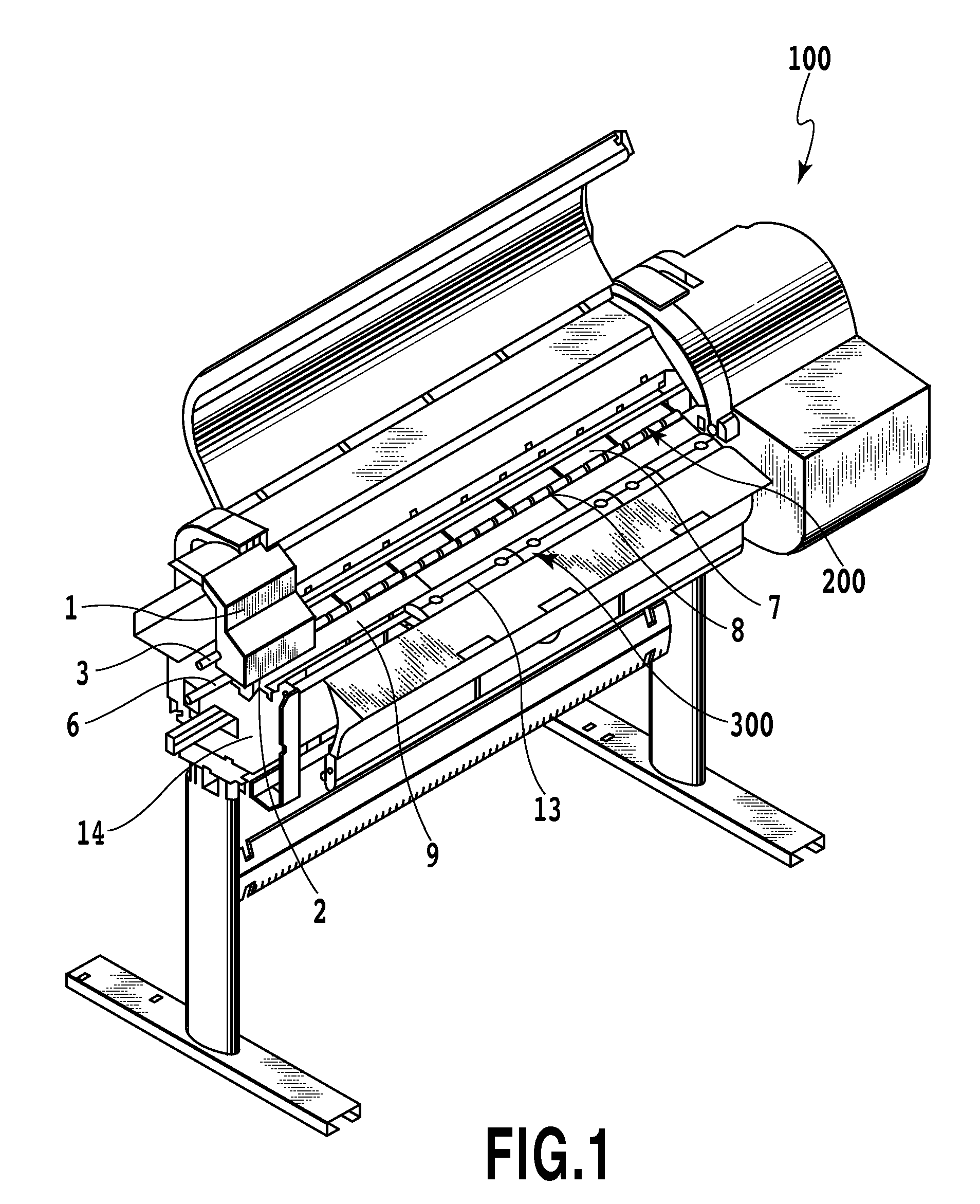
[0033]The configuration of an ink jet printing apparatus according to a first embodiment of the present invention will be described. FIG. 1 is a perspective view of an ink jet printing apparatus 100 according to the present embodiment.

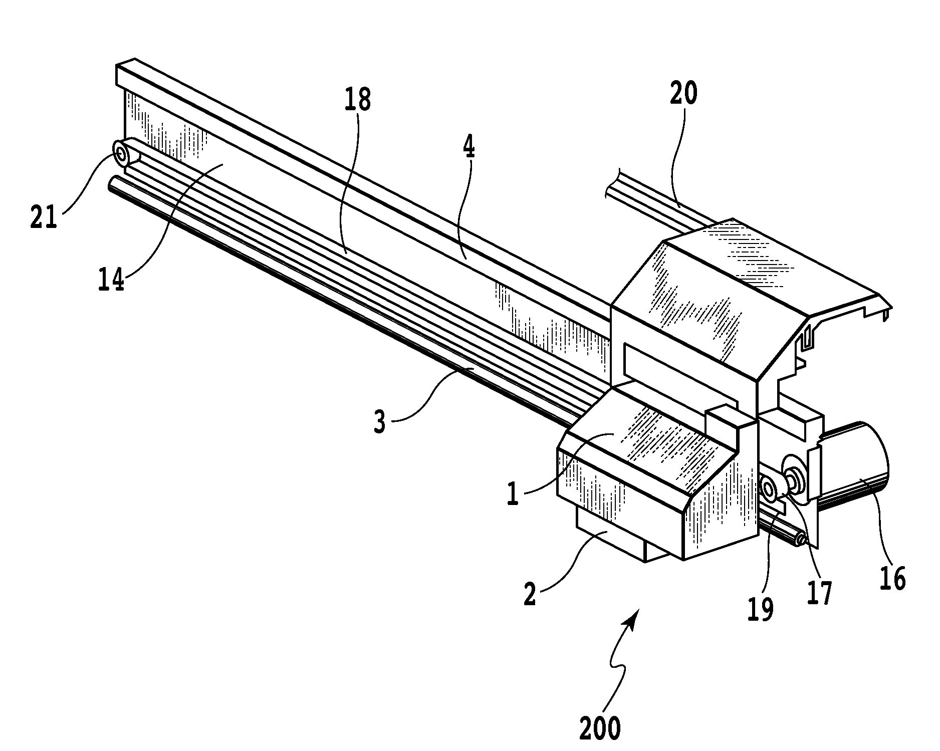
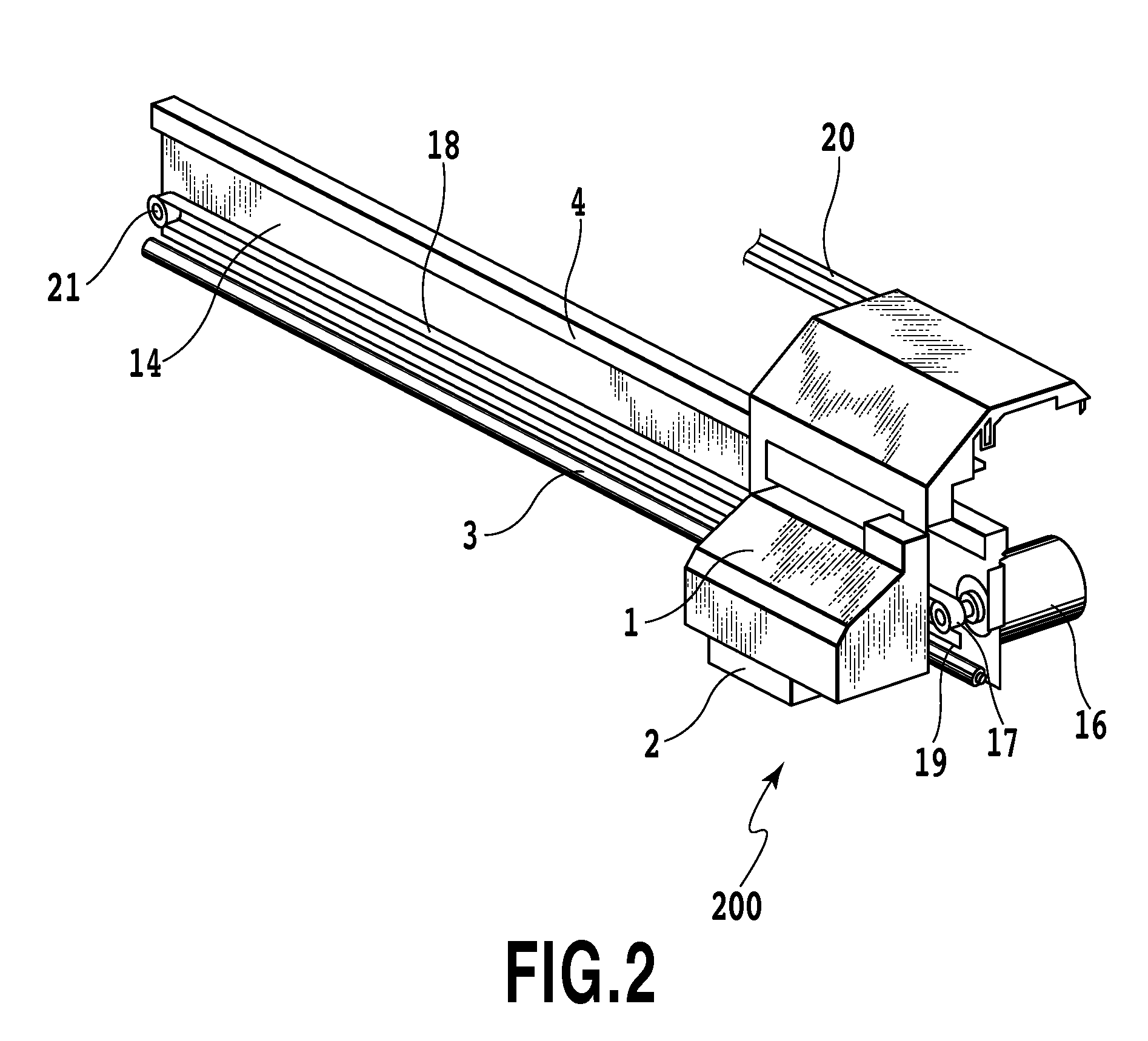
[0034]The ink jet printing apparatus according to the present embodiment is based on the serial scan scheme; a print head 2 is movable in a direction orthogonal to a print medium conveying direction. The ink jet printing apparatus 100 has a carriage 1, a scanning mechanism 200 that reciprocates the carriage 1, a conveying mechanism 300 that conveys a print medium to be printed by the ink jet printing apparatus 100, and a printing apparatus main body.

[0035]The carriage 1 includes a print head 2 mounted thereon for scanning the print medium in a direction orthogonal to the direction in which the print medium is conveyed, while ejecting ink to the print medium for printing. The print head 2, mounted on the carriage 1, has a plurality of ejection ports thr...

second embodiment

[0047]Now, a second embodiment of the ink jet printing apparatus according to the present invention will be described with reference to FIG. 7. Components of the ink jet printing apparatus which can be configured as described above in the first embodiment will not be described. Only differences from the first embodiment will be described. FIG. 7 shows a variation in the number of revolutions of the platen suction fan 11 of the present embodiment during driving. In the present embodiment, the platen suction fan 11 is controlled so as to vary the number of revolutions of the platen suction fan 11 for each of a plurality of scans by the print head 2 within the range of the multipass printing. For example, when the carriage 1 performs printing through six passes as in the case of the present embodiment, the control is performed so as to vary the number of revolutions of the fan for every two scans.

TABLE 2FirstSecondThirdFourthFifthSixthpasspasspasspasspasspass82%82%73%73%78%78%

[0048]Whe...

third embodiment

[0049]Now, a third embodiment of the ink jet printing apparatus according to the present invention will be described with reference to FIG. 8. FIG. 8 shows a method of drivingly controlling the platen suction fan 11. In the present embodiment, for the multipass printing with six passes, the number of revolutions of the platen suction fan 11 is varied plural times during one scan of the print head 2. Thus, during one scan of the carriage 1, the number of revolutions of the platen suction fan 11 is controlled such that the driving speed of the platen suction fan 11 is varied a plurality of times by a driving section of the fan. In the present embodiment, as shown in Table 3, shown below, the number of revolutions of the fan is controlled so as to vary the driving speed in three stages during one scan of the carriage 1.

TABLE 3First passSecond passFirstSecondThirdFirstSecondThirdchangechangechangechangechangechange82%73%78%84%75%82%Third passFourth passFirstSecondThirdFirstSecondThirdch...


PUM


Abstract

The present invention provides an ink jet printing apparatus that inhibits possible density unevenness in an image even though the apparatus performs printing by driving a fan mounted therein. The ink jet printing apparatus according to the present invention includes a print head having an ejection port through which ink is ejected and scanning a print medium in a direction orthogonal to a direction in which the print medium is conveyed, while ejecting droplets to the print medium for printing. A fan performing rotational driving is mounted in the ink jet printing apparatus. The fan is driven so as to vary the number of revolutions thereof for every predetermined amount of scan performed by the print head.

Description

BACKGROUND OF THE INVENTION[0001]1. Field of the Invention[0002]The present invention relates to an ink jet printing apparatus that ejects droplets to print a print medium, and a method of controlling the ink jet printing apparatus.[0003]2. Description of the Related Art[0004]Some ink jet printing apparatuses are of a serial scan type in which printing is performed by a carriage, with a print head mounted thereon, which reciprocates in a direction orthogonal to a print medium conveying direction scanning, while ejecting droplets. In addition to the serial scan type, ink jet printing apparatuses of a full line type are available in which printing is performed by an elongated print head extending over the entire area of the print medium in a width direction thereof and ejecting droplets without scanning. In these ink jet printing apparatuses, the print head and the print medium are spaced from each other, and droplets ejected from the print head cross through the space between the pri...

Claims


Application Information

Patent Timeline
IPC IPC(8): B41J25/308
CPCB41J2/1714
Inventor TSUMOTO, MANABU
Owner CANON KK
Learn More