
Valve timing control apparatus

a timing control and valve technology, applied in the direction of electric controllers, electric control, instruments, etc., can solve problems such as thermal failure of switching elements, and achieve the effect of effectively limiting thermal failures

Active Publication Date: 2009-05-14
DENSO CORP
View PDF7 Cites 13 Cited by
  • Summary
  • Abstract
  • Description
  • Claims
  • Application Information

AI Technical Summary

Benefits of technology

The present invention is a valve timing control apparatus for internal combustion engines that can adjust the timing of valves while limiting thermal damage. It includes an electric motor, stator coils, switching elements, an electric power supply driving means, and a phase adjusting mechanism. The electric power supply driving means sequentially activates the stator coils to drive the motor shaft, which in turn rotates the camshaft to open and close the valves. The phase adjusting mechanism adjusts the timing of the valves based on the rotation of the motor shaft. The electric power supply driving means controls the on-duty ratio of the stator coils to ensure efficient power supply and cooling of the motor. The technical effect of the invention is to provide a reliable and effective solution for valve timing control in internal combustion engines.

Problems solved by technology

Therefore, this switching element may be excessively heated to cause a thermal failure of the switching element.

Method used


Image

  • Valve timing control apparatus
  • Valve timing control apparatus
  • Valve timing control apparatus

Examples


Embodiment Construction

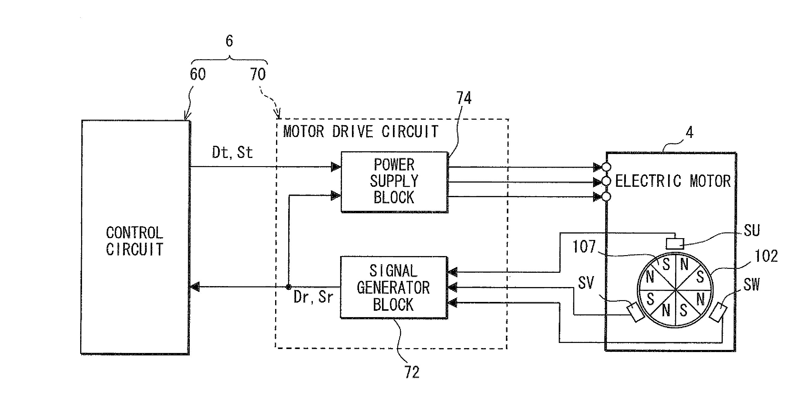
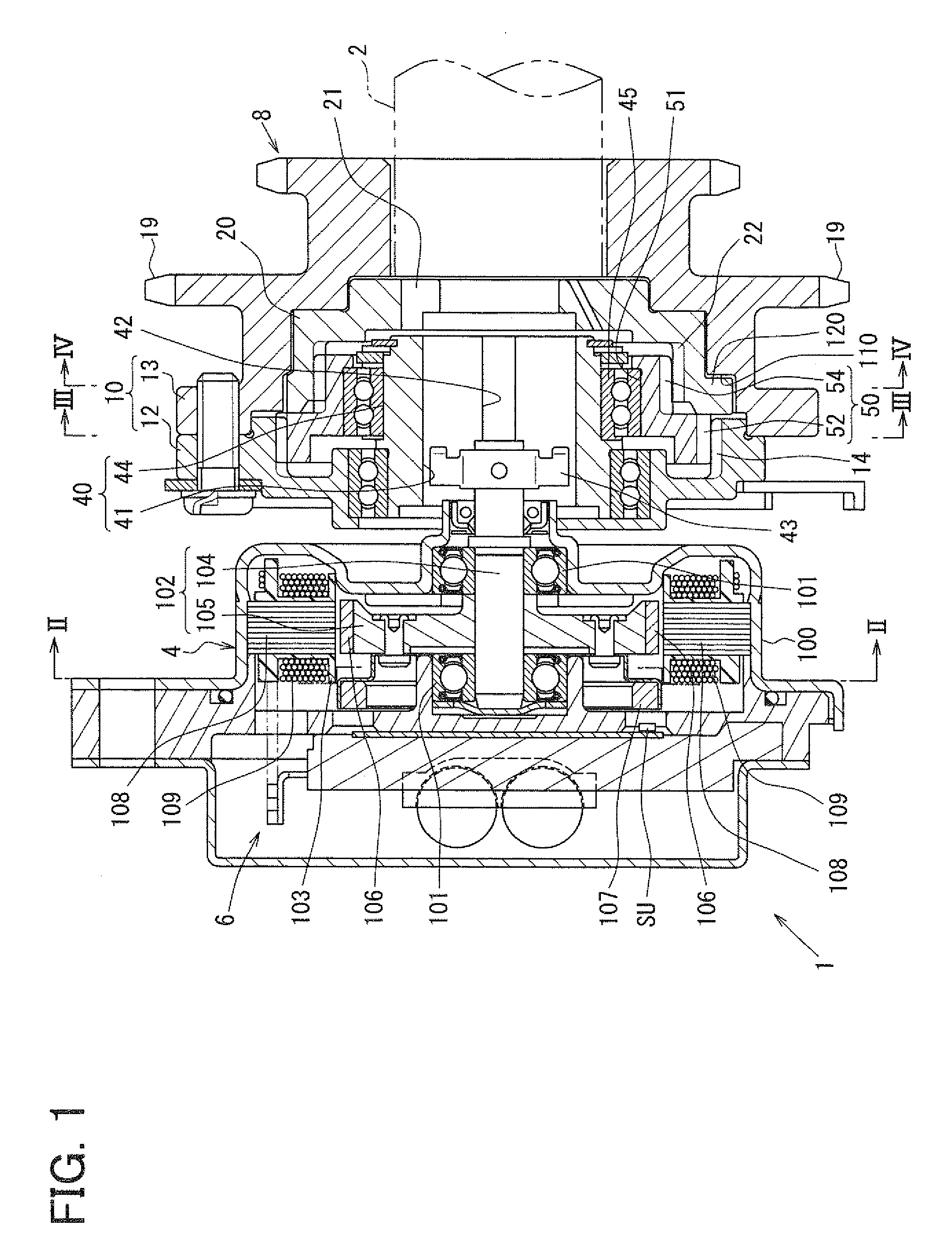
[0021]FIG. 1 shows a valve timing control apparatus 1 according to an embodiment of the present invention. The valve timing control apparatus 1 is installed in a vehicle and is placed in a transmission system, which transmits an engine torque from a crankshaft (not shown) of an internal combustion engine to a camshaft 2. The camshaft 2 of the present embodiment drives intake valves (not shown) among valves of the internal combustion engine to open and close the same. The valve timing control apparatus 1 adjusts the valve timing of the intake valves.

[0022]Hereinafter, a basic structure of the valve timing control apparatus 1 will be described.

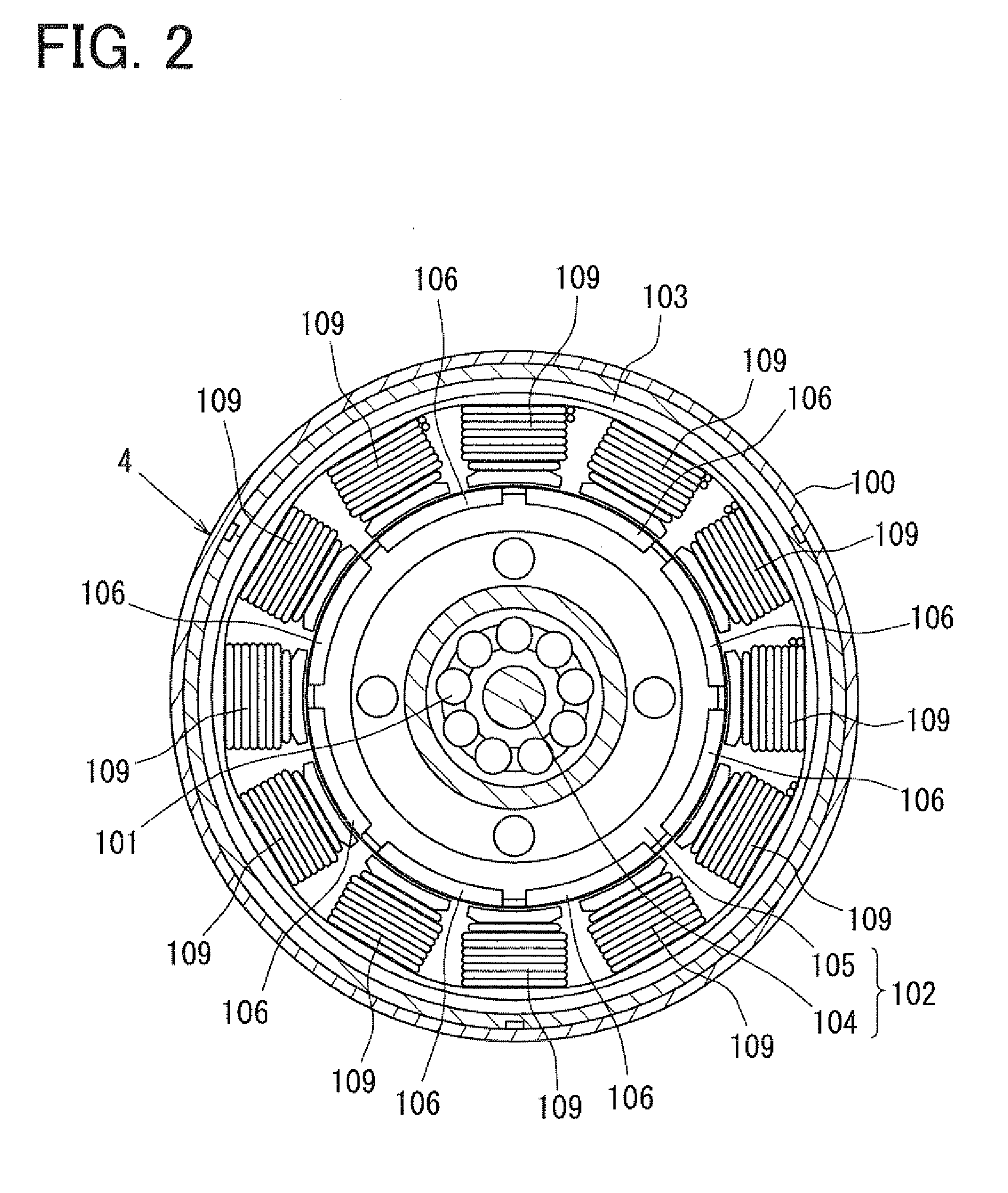
[0023]The valve timing control apparatus 1 includes an electric motor 4, an electric power supply control circuit unit 6 and a phase adjusting mechanism 8. The valve timing control apparatus 1 changes, i.e., adjusts the valve timing, which is determined by a relative phase (referred to as an engine phase) between the crankshaft and the camshaft ...


PUM


Abstract

An electric power supply driver executes duty control of turning on and off of a selected switching element to supply electric power to a corresponding stator coil in a case where an actual rotational direction and a target rotational direction of a motor shaft coincide with each other. Furthermore, the driver sets an on-duty ratio of the selected switching element below a lower limit value, which is at least required to rotate the motor shaft through the power supply to each corresponding stator coil in a case where the actual rotational direction and the target rotational direction do not coincide with each other.

Description

CROSS REFERENCE TO RELATED APPLICATION[0001]This application is based on and incorporates herein by reference Japanese Patent Application No. 2007-294725 filed on Nov. 13, 2007.BACKGROUND OF THE INVENTION[0002]1. Field of the Invention[0003]The present invention relates to a valve timing control apparatus that controls valve timing of at least one valve of an internal combustion engine, which is driven by a camshaft through transmission of a torque from a crankshaft of the internal combustion engine.[0004]2. Description of Related Art[0005]One previously proposed valve timing control apparatus uses a phase adjusting mechanism, which is connected to a motor shaft of an electric motor, to adjust a relative phase (hereinafter, referred to as an engine phase) between a crankshaft and a camshaft according to a rotational state of the motor shaft. For example, Japanese Unexamined Patent Publication No. 2004-350446 teaches a valve timing control apparatus, in which switching elements are c...

Claims


Application Information

Patent Timeline
Patent Type & Authority Applications(United States)
IPC IPC(8): H02P27/04G05B11/28F01L1/352
CPCF01L1/352F01L2201/00F02D2041/2027F01L2820/032F01L2800/00
Inventor UEHAMA, MOTOKIMORII, YASUSHI
Owner DENSO CORP
Learn More