
Discharge Lamp Ballast Apparatus

a technology of discharge lamp and ballast, which is applied in the direction of electric variable regulation, process and machine control, instruments, etc., can solve the problems of hardly detecting a fault due to a cause other than life, hardly determining the cause of the fault, and unable to recognize the process the discharge lamp reaches the malfunction

Inactive Publication Date: 2009-05-14
MITSUBISHI ELECTRIC CORP
View PDF5 Cites 11 Cited by
  • Summary
  • Abstract
  • Description
  • Claims
  • Application Information

AI Technical Summary

Benefits of technology

[0013]The present invention has an advantage of being able to identify, if a fault occurs, the cause of the fault easily. In addition, the present invention has an advantage of being able to decide the lighting state of the discharge lamp, to estimate the deterioration or malfunction of the discharge lamp before a fault occurs, and to notify, when a fault is anticipated, a driver of that fact.

Problems solved by technology

Accordingly, although it can confirm the fact that the faults occur, it can hardly determine the cause of the fault.
In addition, as for the discharge lamp ballast apparatus described in the Patent Document 2, although it can detect the life of the discharge lamp at high accuracy, it can hardly detect a fault due to a cause other than life.
Furthermore, as for the discharge lamp ballast apparatus described in the Patent Document 3, although it can detect a malfunction of the discharge lamp, it cannot recognize the process the discharge lamp reaches the malfunction.
Therefore the conventional discharge lamp ballast apparatuses have a problem in that it is difficult for them to establish the cause of the fault due to the malfunction of the discharge lamp such as early failures of the discharge lamp and deterioration in lighting characteristics due to change over time.
As typical faults whose causes are hardly determined, there are failures in starting the discharge lamp, and going out and blinking during lighting.
These faults can arise because of the life of the discharge lamp, and the malfunction of the discharge lamp (conditions within the discharge lamp alter due to the change over time).
As for the latter case, however, it is difficult to achieve early detection of the malfunction of the discharge lamp.
In addition, since the fault can occur in particular conditions, it is difficult to reproduce the fault to examine the phenomenon, and this makes it difficult to identify the cause of the fault.
Accordingly, as for the fault due to the malfunction of the discharge lamp, there is a problem of being it necessary to normally store the characteristics at the lighting of the discharge lamp to make a decision as to distinctive characteristics of the discharge lamp.

Method used


Image

  • Discharge Lamp Ballast Apparatus
  • Discharge Lamp Ballast Apparatus
  • Discharge Lamp Ballast Apparatus

Examples


embodiment 1

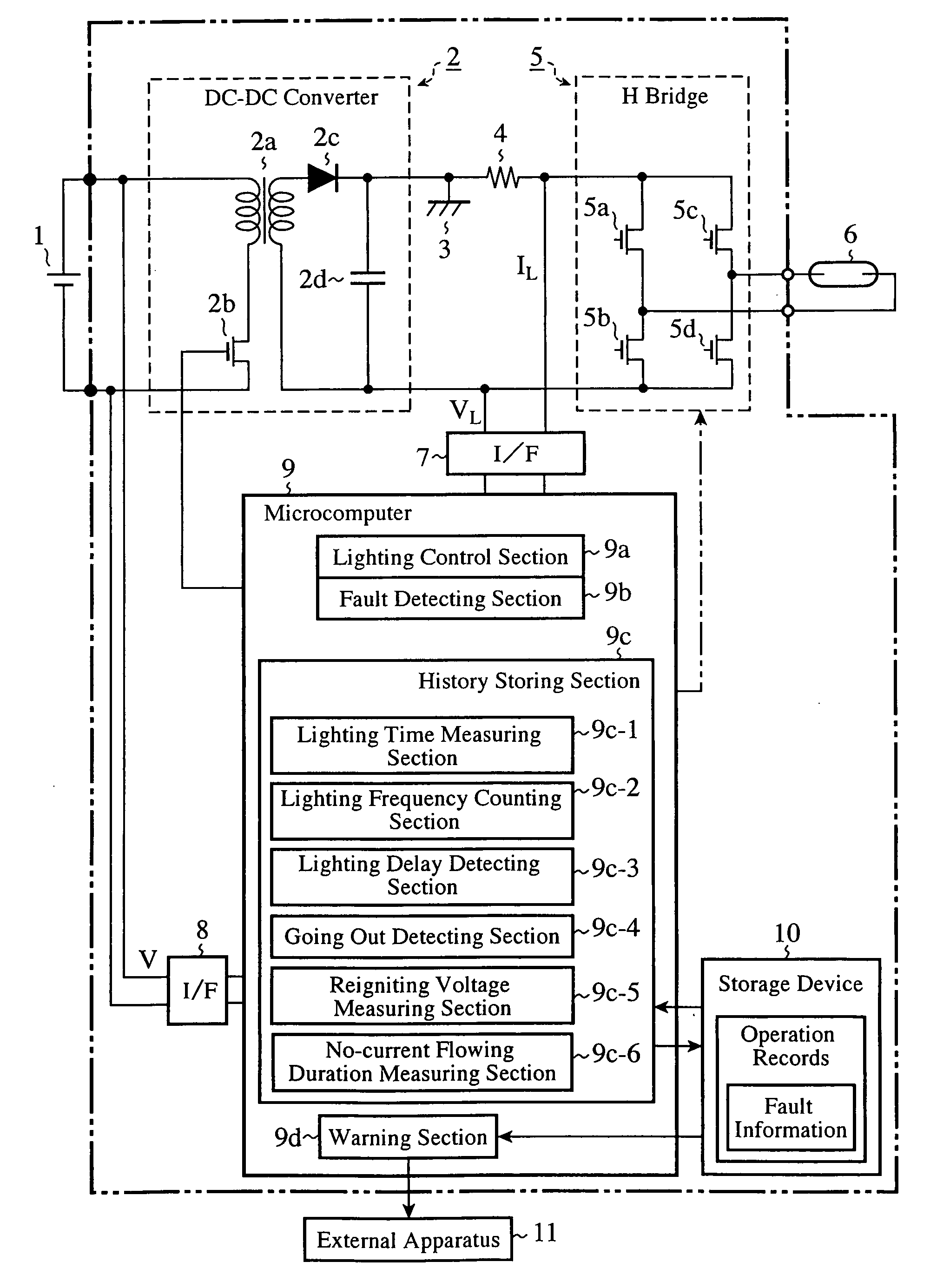
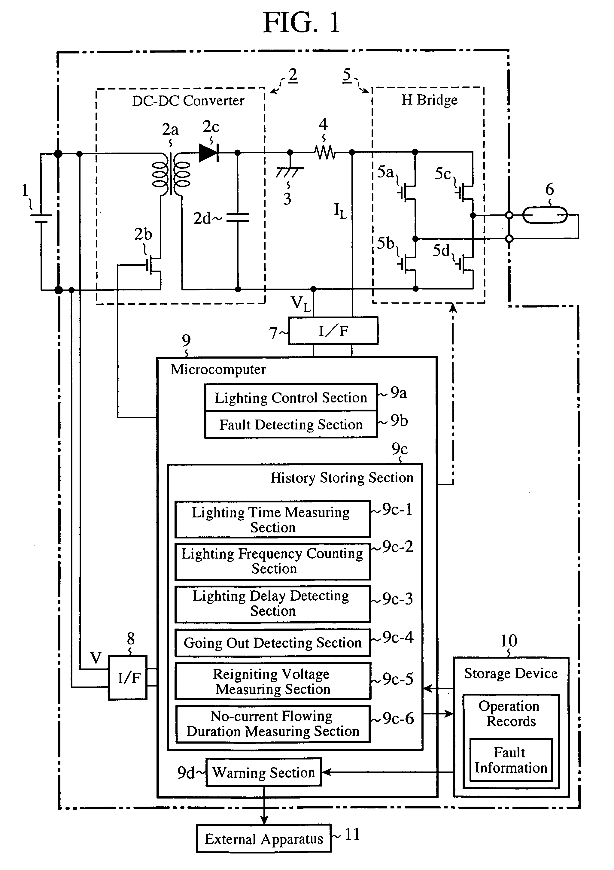
[0027]FIG. 1 is a diagram showing a configuration of a discharge lamp ballast apparatus of an embodiment 1 in accordance with the present invention.

[0028]In FIG. 1, a DC-DC converter (power supply regulating section) 2 is installed for regulating the power fed from a DC power supply 1 such as a battery and for outputting it. The DC-DC converter 2 includes a transformer 2a having a primary winding and a secondary winding, a FET 2b provided at the primary side of the transformer 2a, and a diode 2c connected to the secondary side of the transformer 2a.

[0029]The diode 2c has its cathode side connected to a ground 3 and to an H bridge (discharge lamp driving section) 5 via a discharge lamp current detecting shunt resistance 4 for detecting the discharge lamp current IL. The H bridge 5 includes FETs 5a-5d arranged in an H shape for converting the DC power regulated by the DC-DC converter 2 to AC power, and the AC power passing through the conversion by the H bridge 5 drives a discharge l...


PUM


Abstract

A discharge lamp ballast apparatus includes a fault detecting section 9b of a discharge lamp 6; a first storing section 10 for storing a fault detected; a lighting delay detecting section 9c-3 for detecting lighting delay time from beginning of starting operation to lighting of the discharge lamp; a reigniting voltage measuring section 9c-5 for measuring a discharge lamp voltage immediately after switching of polarity applied to the discharge lamp according to AC lighting; a measuring section 9c-6 for measuring a period of time during which a current does not flow by detecting a discharge lamp current immediately after switching the polarity applied to the discharge lamp according to the AC lighting; a going out counting section 9c-4 for counting a number of times of going out by detecting going out during lighting of the discharge lamp; and a second storing section 9c for storing the lighting delay, reigniting voltage, period of time during which the current does not flow, and number of times of going out as operation records.

Description

TECHNICAL FIELD[0001]The present invention relates to a discharge lamp ballast apparatus, and more particularly to a discharge lamp ballast apparatus suitable for lighting metal halide lamps used as headlights of a vehicle such as an automobile.BACKGROUND ART[0002]As a conventional discharge lamp ballast apparatus with a fault detecting function, there is one that has a section for detecting a power supply voltage and a section for detecting the voltage and current of a discharge lamp; detects a plurality of types of faults according to the discharge lamp voltage, the discharge lamp current and the power supply voltage; stores the number of occurrences of the faults and inhibits lighting the discharge lamp when the number of occurrences of the faults reaches a certain number of times; and enables a worker to check on a display the number of occurrences of the faults stored, thereby making it possible for the worker to check the presence or absence of the faults and their types easil...

Claims


Application Information

Patent Timeline
IPC IPC(8): H05B41/36
CPCH05B41/2925
Inventor OOTSUKA, YASUNORISATO, NAOHITO
Owner MITSUBISHI ELECTRIC CORP
Learn More