
Atmospheric Treater With Roller Confined Discharge Chamber

a technology of atmospheric treater and discharge chamber, which is applied in the direction of corona discharge, papermaking, energy-based chemical/physical/physico-chemical processes, etc., can solve the problems of reducing the quality and homogeneity of treatment, and achieve the effect of facilitating the surface treatment of materials

Active Publication Date: 2009-05-14
ENERCON INDS
View PDF12 Cites 35 Cited by
  • Summary
  • Abstract
  • Description
  • Claims
  • Application Information

AI Technical Summary

Benefits of technology

[0010]The present invention provides a treater system that addresses the above-mentioned concerns and facilitates the surface treatment of materials, especially continuous, bi-dimensional web and sheet materials such as films, papers, textiles and the like, using discharge processes, such as corona, chemical corona and plasma discharge.
[0013]Confining the discharge chamber in close proximity to the discharge allows for more consistent and homogenous treatment. Inadvertent loss of the process gas is reduced or eliminated. Ambient air surrounding the treater is also essentially prevented from entering into the discharge chamber, which could otherwise displace the process gas and / or introduce airborne contaminants into the discharge chamber, which can dilute the process gas being ionized and lead to plasma streamers or other discharge anomalies, which would ultimately diminish the quality and homogeneity of the treatment. In particular, sealing the leading edge of the discharge chamber prevents the boundary layer of air at the surface of the material (typically in a laminar state) from entering the discharge chamber as the material is fed into the treater. This also allows for higher line speeds, greater throughput and significantly less gas consumption, on the order of at least 50%.
[0014]Confining, rather than completely isolating, the discharge chamber is also advantageous because high quality corona, chemical corona and plasma treatments can be achieved at atmospheric pressure without the need for an air tight enclosure and elaborate sealing means of systems requiring that a vacuum be maintained in the discharge chamber. This in turn allows for easier and quicker feeding of the material and less maintenance by reducing the turns required by the material and permitting a more direct feed path. All of this can be achieved with the present invention without sacrificing high line speeds and low consumption of the process gas.
[0016]Thus, surface treatment of materials can be accomplished using corona discharge, a less costly and more readily available form of discharge treatment. Furthermore, there is no need for large, cumbersome forced air exhaust systems for removing and / or decomposing ozone, which are expensive, complicated assemblies and can disrupt conditions in the discharge chamber.
[0017]Moreover, the invention provides for retrofitting existing treater stations by integrating the active electrode and confining roller assembly with existing treaters. For example, a roller electrode and pair of nip rollers can be offered as a kit assembly and installed in existing treaters to define and confine the discharge chamber between the roller electrode, nip rollers and treated material, which can be supported on a backing roll. The roller electrode and roller assembly can be pre-assembled to end mounts, such that the pre-assembly can be readily installed in a treater after modification to accept the end mounts. Other kits can be provided with different electrode and roller configurations, such as those arrangements described below, including for example assemblies with stationary active and ground electrodes and additional rollers.

Problems solved by technology

Ambient air surrounding the treater is also essentially prevented from entering into the discharge chamber, which could otherwise displace the process gas and / or introduce airborne contaminants into the discharge chamber, which can dilute the process gas being ionized and lead to plasma streamers or other discharge anomalies, which would ultimately diminish the quality and homogeneity of the treatment.

Method used


Image

  • Atmospheric Treater With Roller Confined Discharge Chamber
  • Atmospheric Treater With Roller Confined Discharge Chamber
  • Atmospheric Treater With Roller Confined Discharge Chamber

Examples


Embodiment Construction

)

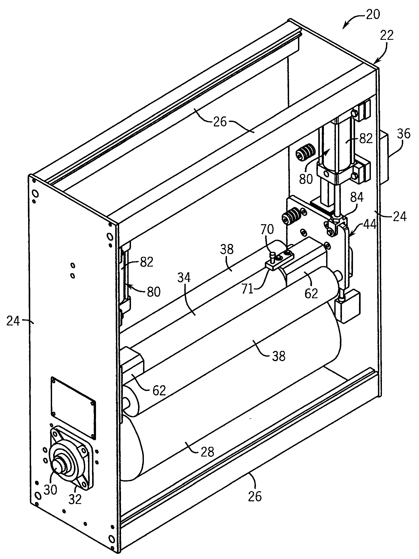
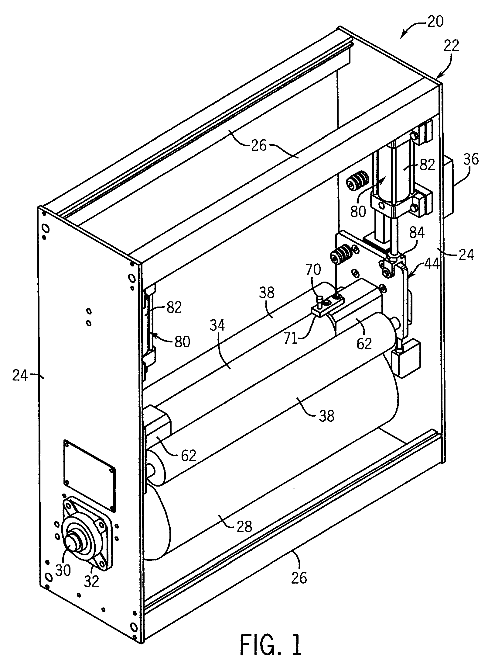
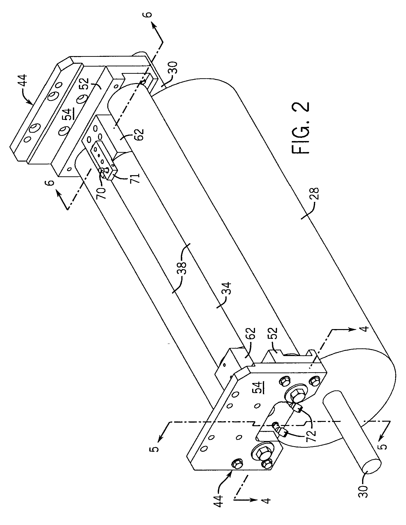
[0033]Referring now to the drawings, FIGS. 1-6 illustrate in detail one embodiment of a treater station 20 according to the present invention. FIG. 7 shows a simplified representation of the discharge chamber defining components of this embodiment to both aid in understanding as well as to facilitate comparison with the various other embodiments described herein. FIGS. 8-14 depict other embodiments in which the present invention can be practiced advantageously, again showing the discharge chambers in simplified form in a way similar to FIG. 7.

[0034]All of the disclosed embodiments have in common certain basic components, including a high voltage power supply, one or more electrodes, and one or more rollers. The various embodiments can also all have elongated electrodes and rollers suitable for treating the full widths of web materials in continuous, line-feed applications. Additionally, each embodiment can be operated to effect various discharge treatments, including for example, c...


PUM

PropertyMeasurementUnit
gap distanceaaaaaaaaaa
widthaaaaaaaaaa

Abstract

A continuous feed discharge surface treater for treating web materials has a discharge chamber where ionization of a process gas occurs defined and contained by one or more rollers. Enhanced chemical coronas and plasmas are achieved by limiting depletion of the gas chemistry from the discharge chamber and dilution or contamination from mixing with drawn in ambient air. Atmospheric coronas can also be achieved in which minimal or no ozone is exhausted from the treater. Various roller and electrode assemblies, including both fixed and rolling electrodes, can be employed.

Description

CROSS-REFERENCE TO RELATED APPLICATIONS[0001]This application claims benefit to U.S. provisional application Ser. Nos. 60 / 986,319, filed Nov. 8, 2007, and 61 / 094,325, filed Sep. 4, 2008.STATEMENT OF FEDERALLY SPONSORED RESEARCH / DEVELOPMENT[0002]Not applicable.BACKGROUND OF THE INVENTION[0003]The invention generally relates to systems for treating the surfaces of materials, especially continuously fed, bi-dimensional materials such as webs, sheets, films, papers, textiles, and the like to enhance the surface characteristics of the materials.[0004]Materials, such as paper, polymer webs and various films, are often used in printing, coating and laminating applications. Many polymers, for example, have chemically inert surfaces with low surface energies providing poor bonding properties. To improve bonding, the surface of the material must be treated to raise the surface tension and thereby improve the application of adhesives and inks. There are a number of known techniques for treatin...

Claims


Application Information

Patent Timeline
Patent Type & Authority Applications(United States)
IPC IPC(8): B01J19/08
CPCB29C59/10B29C59/106B29C59/14H01T19/00B41M5/0011D21H23/22D21H25/04B29C2059/145
Inventor HAMMEN, RICHARD R.ROETHLE, JOSEPHSCHUELKE, GREGORY W.
Owner ENERCON INDS
Learn More