Control Apparatus and Control Method for Hydraulically Driven Cooling Fan
a control apparatus and hydraulically driven technology, applied in the direction of servomotors, fluid couplings, rotary clutches, etc., can solve the problems of affecting the durability of hydraulic equipment, excessive load on hydraulic equipment, and impaired cooling performance, so as to reduce the peak pressure and increase the cost of the apparatus
- Summary
- Abstract
- Description
- Claims
- Application Information
AI Technical Summary
Benefits of technology
Problems solved by technology
Method used
Image
Examples
first working example
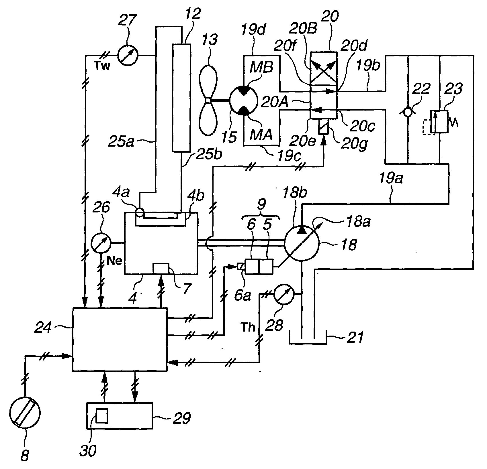
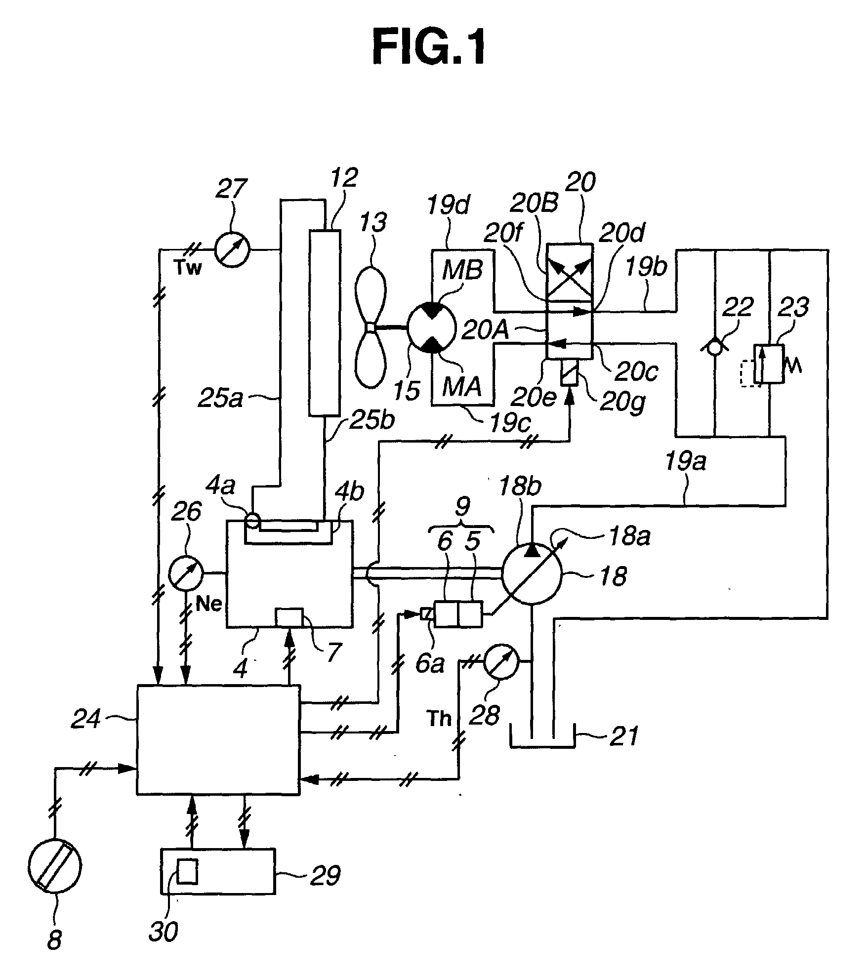
[0114]In this first working example, when the reversing switch 30 is operated so that the reversal processing commencement instruction signal is outputted, control is carried out in which, under the condition that the rotational speed Ne of the engine 4 has decreased to not more than a stipulated rotational speed, the capacity adjusting means 9 is controlled, so as to reduce the capacity of the hydraulic pump 18, and thus reduce the fan rotational speed N, and then the switch position of the switching valve 20 is reversed. Part (a) of FIG. 4 shows the relationship between the time t and the fan rotational speed N in the first working example, and part (b) of FIG. 4 shows transitions between the first reversal processing, normal control, and the second reversal processing on a time chart. That is, upon the control program being started up, reversal processing commencement decision processing 100A (steps 101 to 104) is implemented.
[0115]First, it is judged whether or not reversal proc...
second working example
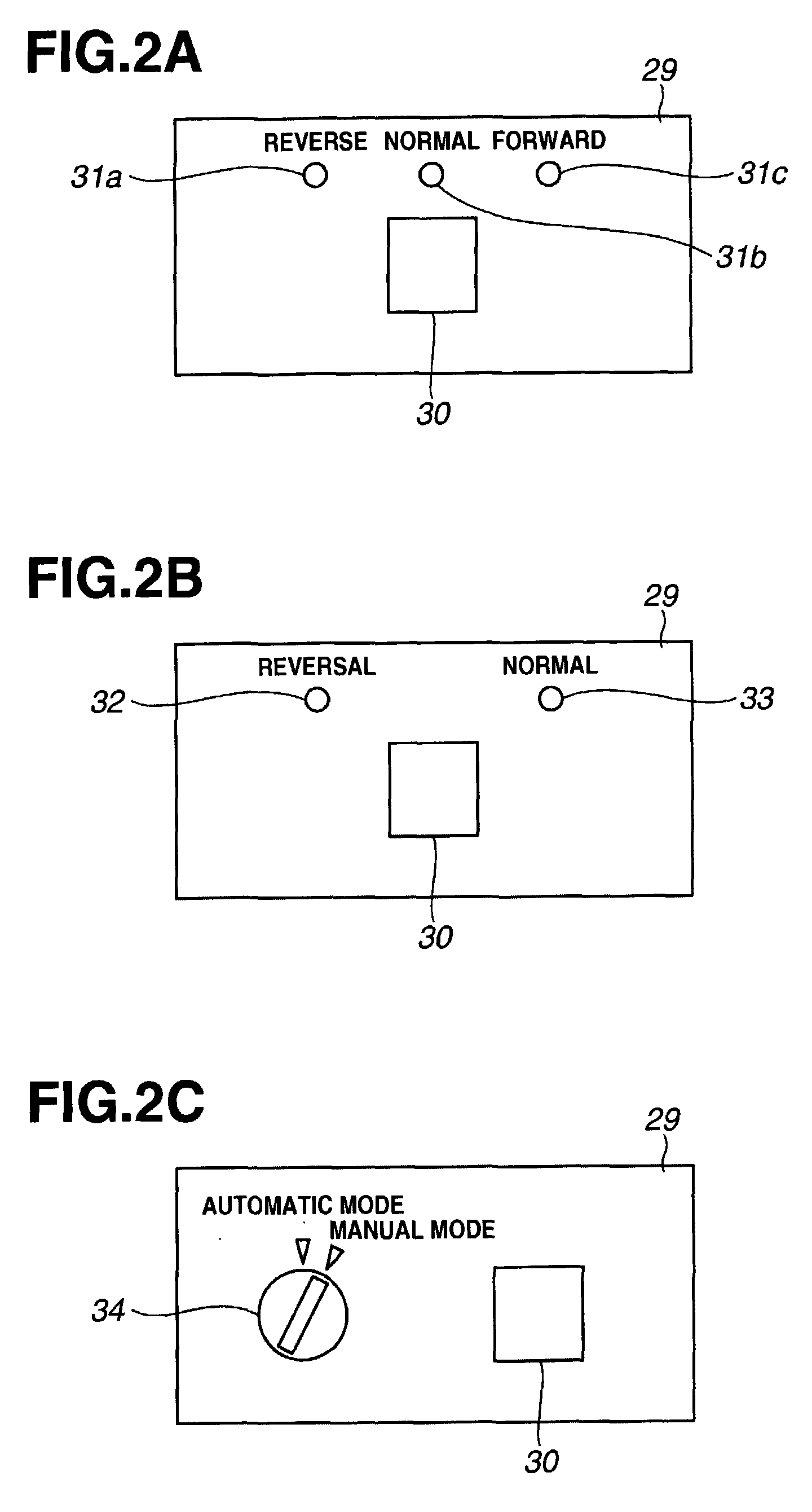
[0149]In the first working example described above, description has been given assuming the case that the reversing switch 30 is constructed as a switch for selecting first reversal processing in which the switching valve 20 is switched from the forward rotation position 20A to the reverse rotation position 20B, and second reversal processing in which the switching valve 20 is switched from the reverse rotation position 20B to the forward rotation position 20A, and the controller 24 implements the first reversal processing upon the reversing switch 30 being operated to select the first reversal processing, and implements the second reversal processing upon the reversing switch 30 being operated to select the second reversal processing. However, as shown in FIG. 2B, implementation is also possible in which the reversing switch 30 is constructed as a switch that instructs reversal processing of switching the switching valve 20 from the forward rotation position 20A to the reverse rota...
third working example
[0157]The lower the oil temperature, the higher the peak pressure becomes, and hence the greater the effect on the durability of the hydraulic equipment, and the greater the effect on the operator.
[0158]Accordingly, in the present working example, the controller 24 carries out control such that the lower the oil temperature value Th, the more the rotational speed N of the hydraulically driven cooling fan 13 is reduced at the times when the switch position of the switching valve 20 is reversed (t3 and t8 in part (a) of FIG. 4), whereby the fan rotational speed N is reduced to the minimum required, so that the peak pressure is reduced reliably.
[0159]Control must thus be carried out such that the lower the oil temperature Th, the lower the fan rotational speed N at each reversal implementation time (t3 and t8 in part (a) of FIG. 4).
[0160]For example, in the case that the oil temperature is a high value Th1, the fan rotational speed required to reduce the peak pressure is a high value N...
PUM
 Abstract
Description
Claims
Application Information
 - R&D
- Intellectual Property
- Life Sciences
- Materials
- Tech Scout
- Unparalleled Data Quality
- Higher Quality Content
- 60% Fewer Hallucinations
Browse by: Latest US Patents, China's latest patents, Technical Efficacy Thesaurus, Application Domain, Technology Topic, Popular Technical Reports.
© 2025 PatSnap. All rights reserved.Legal|Privacy policy|Modern Slavery Act Transparency Statement|Sitemap|About US| Contact US: help@patsnap.com


