
Network System

a network system and network technology, applied in the field of network systems, can solve the problems of inability to correctly recognize the route to the private ip address of the service provider server, and inability to carry out ipsec communication through the napt router. to prevent the complexity of the processing algorithm

Inactive Publication Date: 2009-04-30
HITACHI LTD
View PDF8 Cites 121 Cited by
  • Summary
  • Abstract
  • Description
  • Claims
  • Application Information

AI Technical Summary

Benefits of technology

[0018](B) As one of the methods of solving the problem (A) described above, it may be possible to replace the user terminal side IP address contained in the inside header of the IPsec tunnel model form packet in the service providing server by the global IP address allocated to the NAPT router on the user terminal side and to interpret the packet. Owing to this measure, the service providing server can correctly recognize the route to the user terminal side IP address. In addition, the possibility of overlap of the IP address with hosts existing inside the service providing server side LAN and other user terminal side LAN can be eliminated. On the other hand, when two user terminals existing inside LAN under the same NAPT router communicate with the same service providing server for user terminal side port number field of the inside TCP / UDP header of the IPsec tunnel mode form packet (source port number 2121 in FIG. 21 in the case of packet sent by user terminal) by using the same port number, the service providing server cannot know from which user terminal the received packet is sent.
[0031]In addition, the communication method of the invention does not need to judge whether or not the NAPT router exists on the communication line with the exception of the case where the service providing server dynamically acquires the global IP address of its own as well as the WAN side port number of the outside UDP header from the NAPT router. Therefore, the processing algorithm can be prevented from getting much more complex owing to the addition of the communication method of the invention to minimum.

Problems solved by technology

On the premise described above, NAPT operates for the IPsec packet in the NAPT router but IPsec communication through the NAPT router is not always possible by this arrangement alone.
Nonetheless, IPsec communication through the NAPT routers cannot be carried out correctly owing to the following problems occurring depending on the installation positions of the routers.
The following two problems occur in IPsec communication through the NAPT router when the NAPT router exists on the user terminal side.
However, the private IP address of the user terminal is the one that is allocated under management different from LAN on the service providing server side and there is the possibility that the service providing server fails to correctly recognize the route to the private IP address.

Method used


Image

  • Network System
  • Network System
  • Network System

Examples


first embodiment

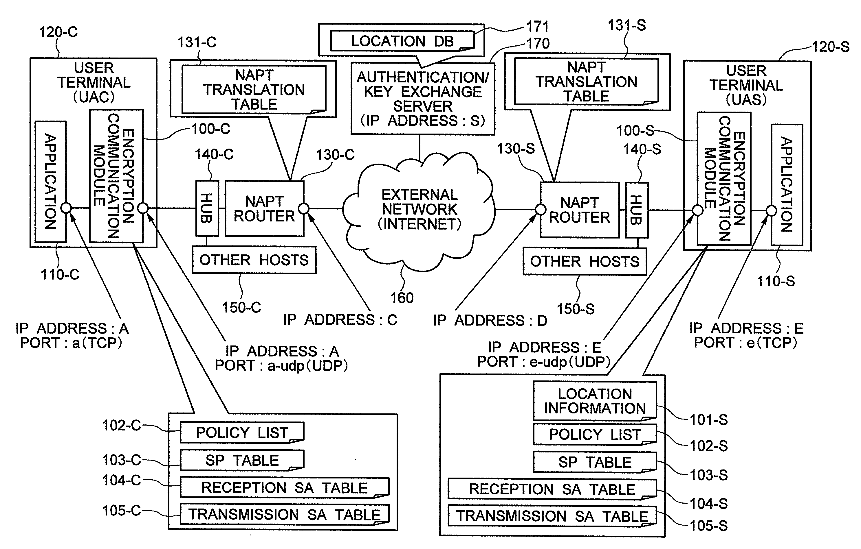
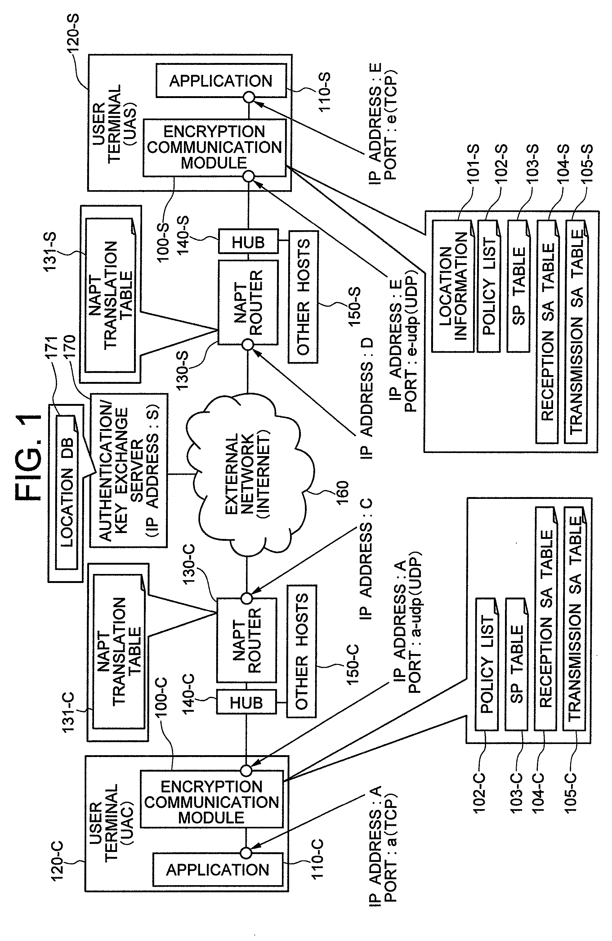
[0071]FIG. 1 shows a network construction of a system as an application object of an encryption communication module having a communication method of the invention in the first embodiment.

[0072]A user terminal 120-C and a service providing server 120-S are connected to an external network 160 such as the Internet through NAPT routers 130-C and 130-S, respectively. The network between the user terminal 120-C and the NAPT router 130-C is a user terminal side LAN and the network between the NAPT router 130-C and the NAPT router 130-S is WAN. The network between the NAPT router 130-S and the service providing server 120-S is a service providing server side LAN.

[0073]Generally, private IP addresses are used for the user terminal side LAN and the service providing server side LAN and a global IP address is used for WAN. It will be assumed that this arrangement is employed in this embodiment, too, but such an address allocation is not always essential. It will be assumed that a private IP ...

second embodiment

[0240]FIG. 27 shows a network construction of a system as an operation object of an encryption communication module having a communication method of the invention in a second embodiment of the invention.

[0241]In the second embodiment, the encryption communication modules 2700-C and 2700-S operate inside NAPT routers 2735-C and 2735-S with encryption communication function but not inside the user terminal 2720-C and the service providing server 2720-S. Inside the NAPT routers with encryption communication function 2735-C and 2735-S, encryption communication modules 2700-C and 2700-S operating similarly to the encryption communication modules 110-C and 100-S in the first embodiment and NAPT router modules 2730-C and 2730-S operating similarly to the NAPT routers 130-C and 130-S in the first embodiment operate inside the NAPT routers with encryption communication function 2735-C and 2735-S. Only applications 110-C and 110-S operate inside the user terminal 2720-C and the service provid...

third embodiment

[0269]FIG. 34 shows a network construction of a system as an application object of the encryption communication module having the communication method of the invention in a third embodiment.

[0270]In the case where the NAPT is applied to only the user terminal side and the global IP address is directly allocated to the service providing server as in this embodiment, too, encryption communication of the application can be executed without any problem. In this embodiment, the encryption communication modules are built in the user terminal and the service providing server but the encryption communication module on the user terminal side may be built in the NAPT router without any problem as in the second embodiment.

[0271]FIG. 35 is a sending / receiving sequence diagram for sending a data packet from a UAC side application to a UAS side application by using an encryption communication line when the encryption communication line is established between the UAC and UAS.

[0272]Since the NAPT r...


PUM


Abstract

An encryption communication module on the side of a service providing server reports a global IP address allocated to an NAPT router on the service providing server side and a port number of an outside UDP header used on the global side to an authentication / key exchange server. When receiving an encryption packet from an encryption communication module on the user terminal side, the encryption communication module on the service providing server side overwrite a source / destination IP address of an inside IP header by a source / destination IP address of an outside IP header. The encryption communication module further changes a source port number of an inside TCP•UDP header to a unique value for each communication session in the encryption communication having the same source IP address in the outside IP header. The inverse header change is made when the packet is transmitted to the encryption communication module of the user terminal side.

Description

INCORPORATION BY REFERENCE[0001]The present application claims priority from Japanese application JP2007-278305 filed on Oct. 26, 2007, the content of which is hereby incorporated by reference into this application.BACKGROUND OF THE INVENTION[0002]1. Field of the Invention[0003]In a system in which a client and a first server exchange key information through a second server trusted by both of the parties and execute encryption tunneling communication by using the key, this invention relates to a method that makes it possible to carry out communication even when a network / address translation apparatus exists on a communication line between the client and the first server.[0004]2. Description of the Related Art[0005]Encryption of communication has been carried out daily in an IP (Internet Protocol) network such as the Internet as a method for protecting the communication content from a threat of security typified by tapping on the communication line. Typical examples of various kinds ...

Claims


Application Information

Patent Timeline
Patent Type & Authority Applications(United States)
IPC IPC(8): H04L9/00H04L29/06H04L9/08H04L12/22H04L12/46H04L12/66H04L12/70
CPCH04L29/12377H04L29/12424H04L29/1249H04L61/2517H04L63/164H04L61/256H04L63/0428H04L63/08H04L61/2535
Inventor TSUGE, MUNETOSHIHOSHINO, KAZUYOSHIKAJI, TADASHI
Owner HITACHI LTD
Learn More