Lean premixed, radial inflow, multi-annular staged nozzle, can-annular, dual-fuel combustor

Inactive Publication Date: 2009-04-30
GENERAL ELECTRIC CO
View PDF14 Cites 112 Cited by
  • Summary
  • Abstract
  • Description
  • Claims
  • Application Information

AI Technical Summary

Benefits of technology

[0018]The present invention relates to an apparatus and method creating three independent combustion zones in a gas turbine combustor with a lean premixed, radial inflow, multi-annular, staged nozzle, thereby providing stable combustion with low nitrogen oxide (NOx) emissions.
[0019]Briefly in accordance with one aspect of the present invention, a lean premixed, radial inflow, multi-annular, staged nozzle for creating three independent combustion zones within a can-annular, dual-fuel gas turbine combustor is provided. The lean premixed, radial inflow, multi-annular, staged nozzle (hereinafter referred to as a single large radial nozzle) includes a pilot zone fueled by a center cartridge; a flame holder zone fueled by an inner main gas fuel; a main flame zone fueled by an outer main gas fuel; a main radial swirler for mixing a portion of incoming air to the nozzle with the inner main gas fuel supply and the outer main gas fuel supply; an endcover; and means for controlling the ratio of pilot gas fuel supplied, inner main gas fuel supplied, and an outer main gas fuel supplied.
[0021]In accordance with a third aspect of the present invention, a method is provided for utilizing a lean premixed, radial inflow, multi-annular, staged nozzle (hereinafter referred to as a single large radial nozzle) with independent combustion zones, wherein the single large radial nozzle includes a pilot zone, a flame holder zone and a main zone, within a gas turbine combustor for providing stable combustion with low Nitrogen Oxide (NOx) emissions. The method includes providing a large supply of air to the nozzle; intra-nozzle staging; breaking up of the heat release into a multiplicity of discrete zones in space; distributing the heat release in time; and ventilating a downstream central recirculation zone.

Problems solved by technology

These pressure oscillations can severely limit the operation of the device and in some cases can even cause physical damage to combustor hardware.
This direct injection reduces the local temperature and strength of the recirculation, producing an adverse effect on flame stability.
This approach, however, creates a complicated and expensive assembly.
Also, distributing the air and fuel uniformly to the cluster of premixing fuel nozzles at the headend is difficult and generally results in less than ideal, uniform air flow to all the nozzles, or a substantial amount of parasitic pressure drop / loss.
Swirl-stabilized, lean premixed (LP) combustion tends to be highly susceptible to combustion-driven oscillations (dynamic instability) compared to conventional, diffusion style combustion.
For such lean mixtures, slight, periodic variations in local fuel-to-air mixture ratio results in relatively large, periodic variations in local heat release and heat-release rates—even including local, periodic flame extinction.
As present LP combustors become leaner and more spatially uniform to meet increasingly lower NOx emissions, and are increasingly required to meet those emission targets while running on a broadening range of fuels, the risk of encountering unacceptably high levels of combustion dynamics goes up for a given system.
Although, large single-nozzle DLN, low-NOx can-annular gas-turbine combustion systems have been tried previously, most have failed due to operability, durability, and emissions problems.
The downside of skewing the fuel distribution in the combustor is that hotter temperature zones are created that drive NOx production.
Thus, if too much skewing is required to squash dynamics or instability, the breaching of regulatory NOx emissions limits could occur, possibly putting the unit out of commission.
LP combustion dynamics in industrial gas turbines are typically abated passively in a few ways, usually a trial and error process, which can be expensive and uncertain.

Method used


Image

  • Lean premixed, radial inflow, multi-annular staged nozzle, can-annular, dual-fuel combustor
  • Lean premixed, radial inflow, multi-annular staged nozzle, can-annular, dual-fuel combustor
  • Lean premixed, radial inflow, multi-annular staged nozzle, can-annular, dual-fuel combustor

Examples


Embodiment Construction

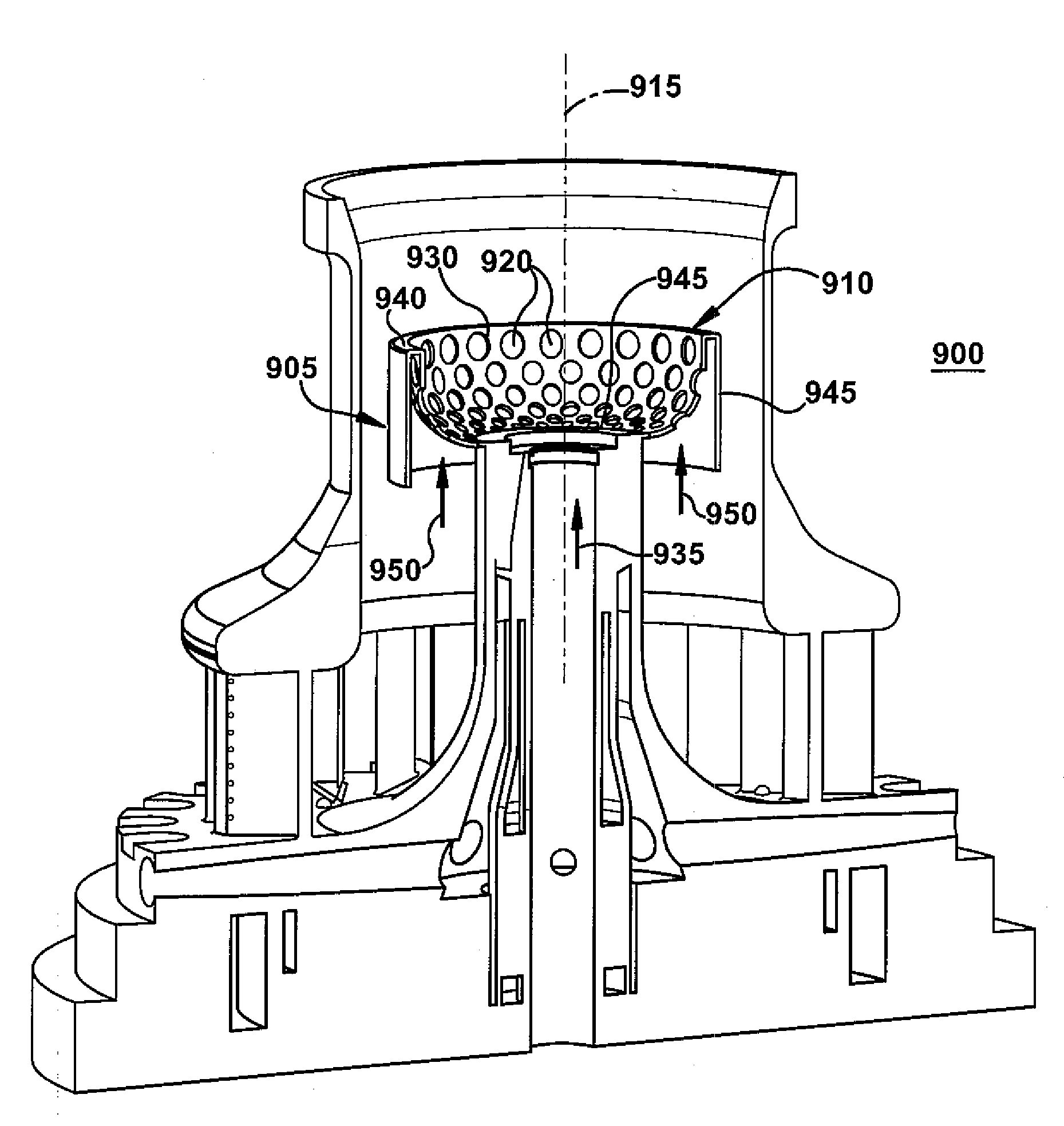
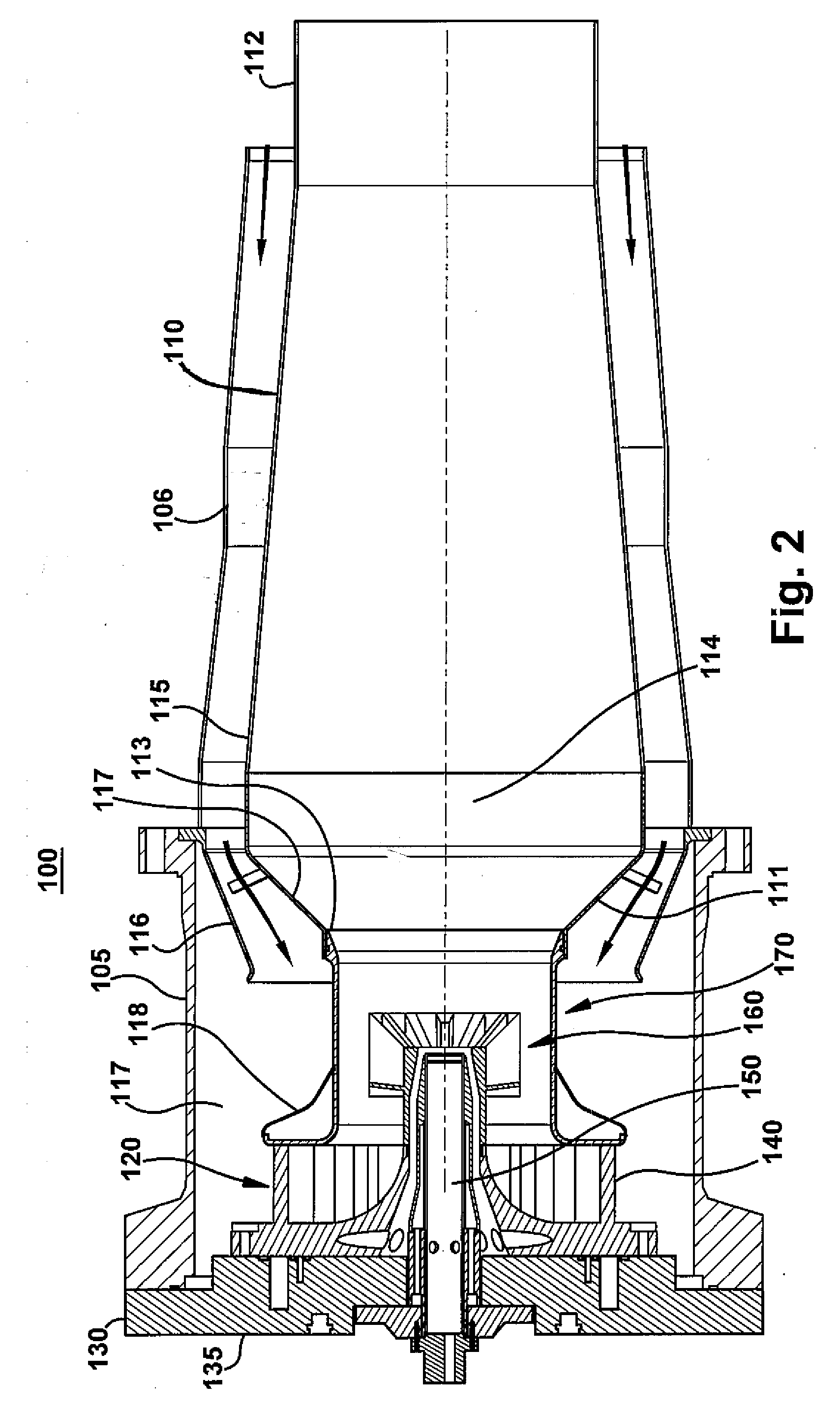
[0039]The following embodiments of the present invention have many advantages, including several innovative and unique features: (1) allowing for multiple (e.g., six) premixing nozzles (per can) and a combustor-chamber cap to be replaced with just one large radial nozzle and a liner modification, thereby achieving a significant part-count reduction, a cost savings, and a dramatic simplification of the combustor's head-end; (2) using a dome-diffuser design to backside, convectively cool the liner's dome, while, simultaneously recovering static pressure prior to premixing the fuel and air in the large radial nozzle, thereby causing less parasitic pressure loss and malting more air available for premixing; (3) providing the capacity to rapidly (e.g. <3 msec) and thoroughly vaporize and mix large quantities of fuel (˜2 lbm / sec) and air (˜60 lbm / sec) at a relatively low pressure drop (e.g., <4%); and (4) using either gas fuel or liquid fuel, it is more robust dynamically and less prone t...


PUM


Abstract

A lean premixed, radial inflow, multi-annular staged nozzle for creating three independent combustion zones within a can-annular, dual-fuel gas turbine combustor is provided. The nozzle includes a pilot zone fueled by a gas pilot nozzle and center cartridge; a flame holder zone fueled by an inner main gas fuel; a main flame zone fueled by an outer main gas fuel; a main radial swirler for mixing a portion of incoming air to the nozzle with the inner main gas fuel supply and the outer main gas fuel supply; an endcover; and means for controlling the ratio of an inner main gas fuel supplied and an outer main gas fuel supplied.

Description

BACKGROUND OF THE INVENTION[0001]The invention relates generally to gas turbine combustors and more specifically to a lean premixed, radial inflow, multi-annular staged nozzle for a can-annular dual-fuel combustor that dramatically reduces or eliminates combustion dynamics.[0002]FIG. 1 illustrates a prior art combustor for a heavy-duty industrial gas turbine 10, which includes a compressor 12 (partially shown), a plurality of combustors 14 (one shown for convenience and clarity), and a turbine 16 (represented by a single blade). Although not specifically shown, the turbine 16 is drivingly connected to the compressor 12 along a common axis. The compressor 12 pressurizes inlet air, which is then reverse flowed to the combustor 14 where it is used to cool the combustor 14 and to provide air to the combustion process. Although only one combustor 14 is shown, the gas turbine 10 includes a plurality of combustors 14 located about the periphery thereof. A transition duct 18 connects the ou...

Claims


Application Information

Patent Timeline
IPC IPC(8): F23C5/08
CPCF23R3/14F23R3/286Y02T50/675F23R3/36F23R3/343Y02T50/60
Inventor BOARDMAN, GREGORY A.JOHNSON, THOMAS E.MCCONNAUGHHAY, JOHNIE F.SANYAL, ANURADHA
Owner GENERAL ELECTRIC CO
Why Eureka
Try Eureka