Stuck Vehicle with Time and Pedal Related Traction Control
- Summary
- Abstract
- Description
- Claims
- Application Information
AI Technical Summary
Benefits of technology
Problems solved by technology
Method used
Image
Examples
Embodiment Construction
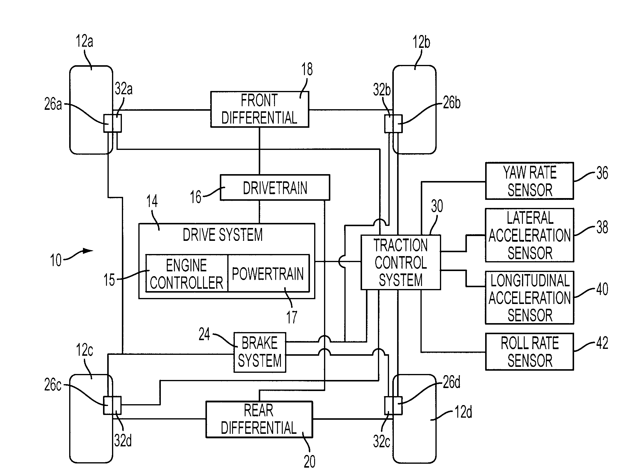
[0016]FIG. 1 is a block diagram of a vehicle 10 having a traction control system. As shown in FIG. 1, vehicle 10 may comprise wheel and tire assemblies 12a, 12b, 12c, and 12d. A drive system 14 coupled to a drivetrain 16 may provide power to the wheel and tire assemblies 12a-d through a front differential 18 and rear differential 20. Drive system 14 may include an engine controller 15 and a powertrain 17. Engine controller 15 may be a microprocessor-based system. Powertrain 17 may provide power by a power generating unit, such as an internal combustion engine, a hybrid electric system, an electric drive system, or a fuel cell system. Engine controller 15 may control the amount of torque and thus the amount of slip generated at each of the wheels. Drive system 14 may vary the amount of power output to effect a change in torque at wheel and tire assemblies 12a-d.
[0017]Drive system 14 may provide torque through drivetrain 16, which may include a transmission, front differential 18 and...
PUM
 Abstract
Description
Claims
Application Information
 - R&D
- Intellectual Property
- Life Sciences
- Materials
- Tech Scout
- Unparalleled Data Quality
- Higher Quality Content
- 60% Fewer Hallucinations
Browse by: Latest US Patents, China's latest patents, Technical Efficacy Thesaurus, Application Domain, Technology Topic, Popular Technical Reports.
© 2025 PatSnap. All rights reserved.Legal|Privacy policy|Modern Slavery Act Transparency Statement|Sitemap|About US| Contact US: help@patsnap.com


