
Valve timing controller

a timing controller and valve technology, applied in the direction of valve arrangements, machines/engines, mechanical equipment, etc., can solve the problems of deteriorating the control accuracy of the valve timing, large fluctuation of the vane rotor relative to the housing, etc., and achieve the effect of enhancing the variation speed of the engine rotational phase in a retarding direction and enhancing the engine rotational phase in an advance direction

Inactive Publication Date: 2009-04-30
DENSO CORP
View PDF1 Cites 19 Cited by
  • Summary
  • Abstract
  • Description
  • Claims
  • Application Information

AI Technical Summary

Benefits of technology

[0006]The present invention is made in view of the above matters, and it is an object of the present invention to provide a valve timing controller which can realize a valve timing suitable for the internal combustion engine.
[0009]Hence, when the engine rotational phase is held at the target phase region, it can be restricted that the operating fluid flows out from the advance chamber and the retard chamber. Furthermore, it can be restricted that the inner pressure of the advance chamber and the retard chamber becomes negative. Thereby, a fluctuation of the second rotating member relative to the first rotating member can be restricted. Therefore, the engine rotational phase can be held at the target phase region so that a suitable valve timing can be achieved.
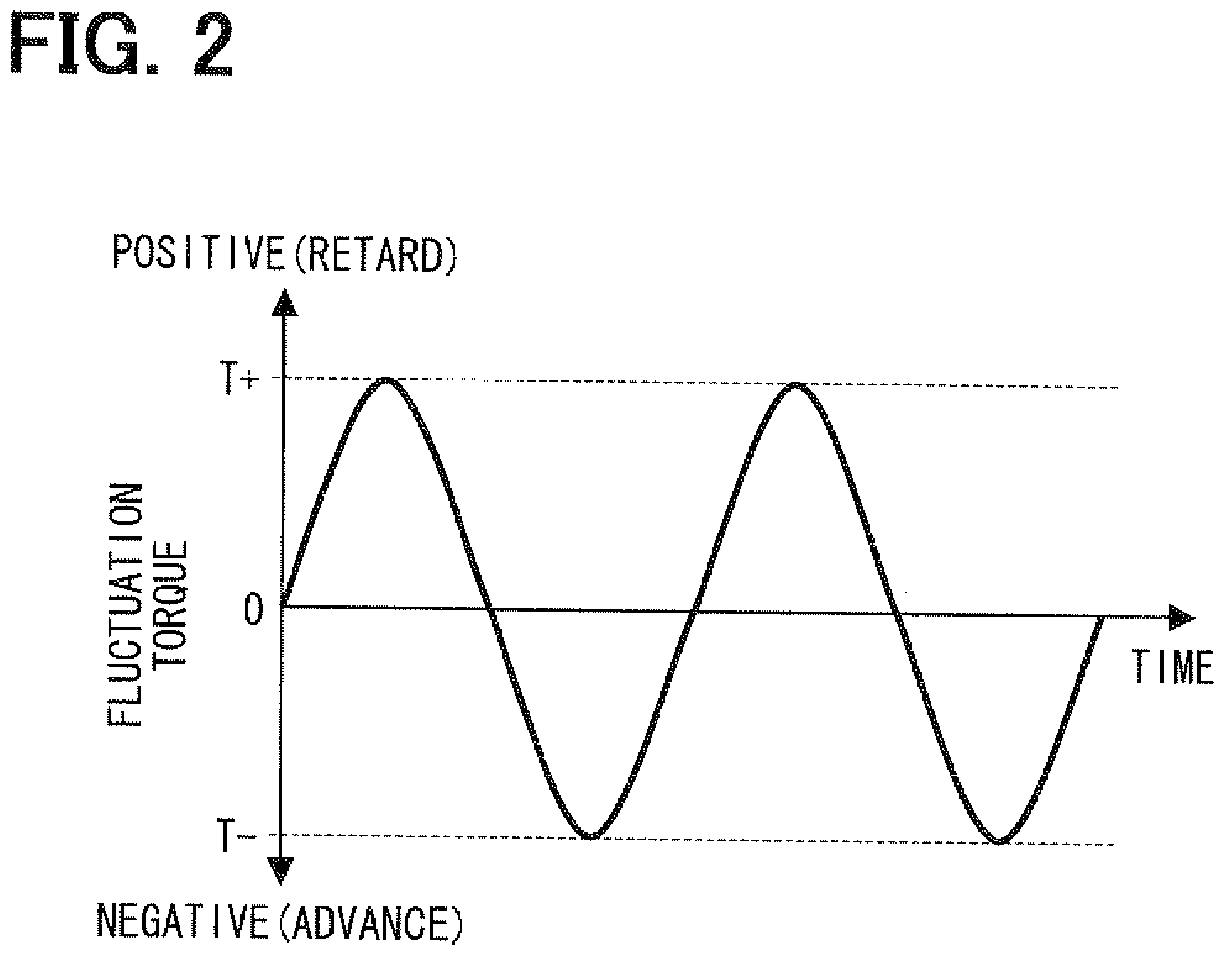
[0017]In a case that the camshaft is advanced, the advance chamber communicates with the supply port and the retard chamber communicates with the drain port. Thus, when the operating fluid in the retard chamber is compressed by the fluctuation torque, the operating fluid in the retard chamber can be discharged through the drain port. When the operating fluid in the advance chamber is compressed by the fluctuation torque, the advance check valve restricts the operating fluid flow flowing from the advance chamber to the supply chamber, whereby the outflow of the operating fluid from the advance chamber can be restricted. Therefore, a variation speed of the engine rotational phase in an advance direction can be enhanced, so that the suitable valve timing can be early achieved.
[0018]In a case that the camshaft is retarded, the retard chamber communicates with the supply port and the advance chamber communicates with the drain port. Thus, when the operating fluid in the advance chamber is compressed by the fluctuation torque, the operating fluid in the advance chamber can be discharged through the drain port. When the operating fluid in the retard chamber is compressed by the fluctuation torque, the retard check valve restricts the operating fluid flow flowing from the retard chamber to the supply chamber, whereby the outflow of the operating fluid from the retard chamber can be restricted. Therefore, a variation speed of the engine rotational phase in a retard direction can be enhanced, so that the suitable valve timing can be early achieved.

Problems solved by technology

If the operating oil is flown out from one of the advance chamber and the retard chamber due to the large fluctuation torque, a negative pressure is arose in the other chamber to draw air through a clearance gap, which may cause a large fluctuation of the vane rotor relative to the housing.
Such a fluctuation of the vane rotor may deteriorate a control accuracy of a valve timing.

Method used


Image

  • Valve timing controller
  • Valve timing controller
  • Valve timing controller

Examples


first embodiment

[0027]Hereafter, the present invention is described.

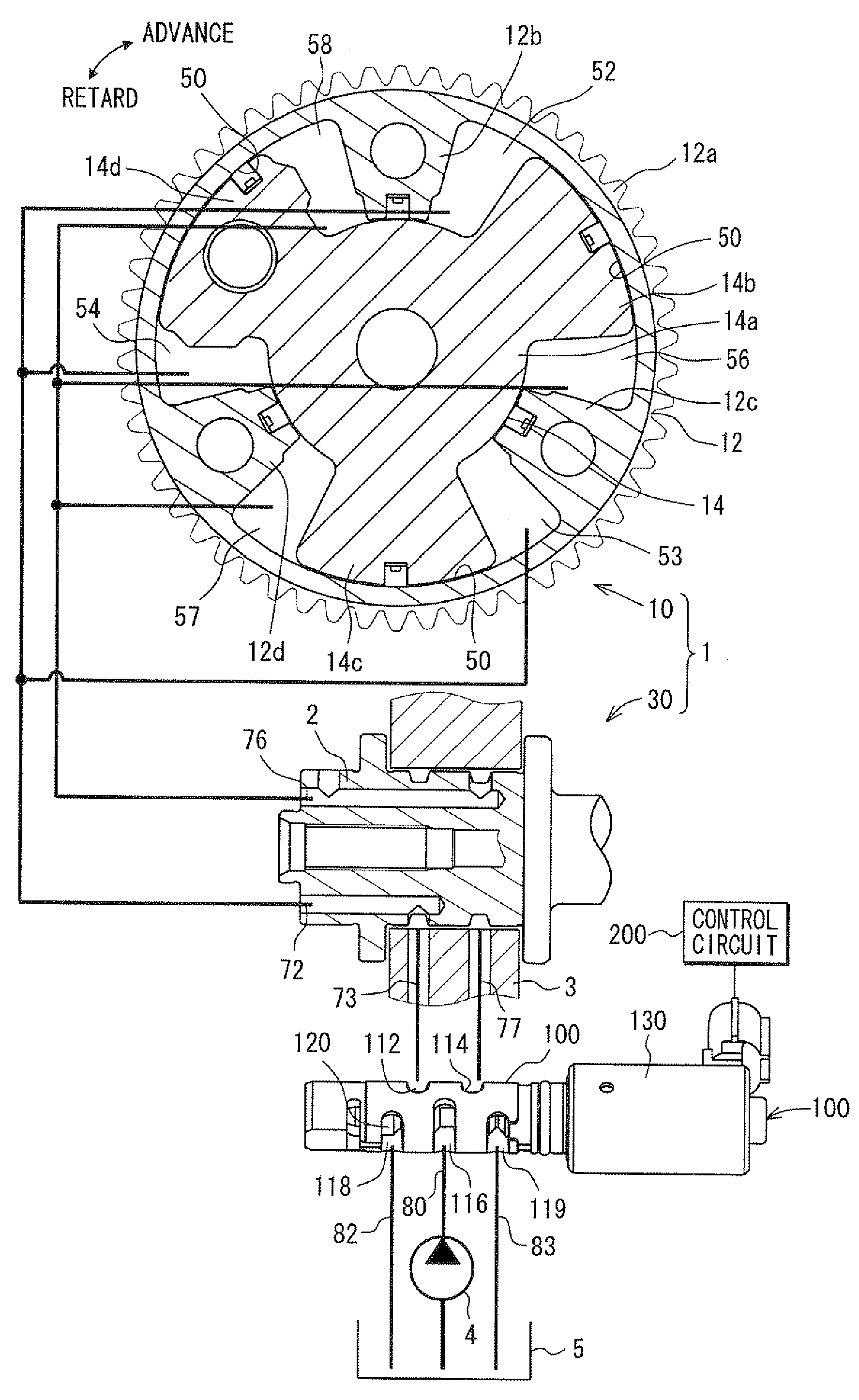
[0028]FIG. 1 shows a first embodiment of a valve timing controller 1 which is applied to an internal combustion engine for a vehicle. The valve timing controller 1 is driven by an operating fluid such as operating oil to adjust a valve timing of an intake valve.

(Basic Structure)

[0029]A basic structure of the valve timing controller 1 will be described hereinafter. The valve timing controller 1 includes a driving unit 10 and a control unit 30. The driving unit 10 transmits a driving force of a crankshaft (not shown) to a camshaft 2. The control unit 30 controls an operating oil supply to the driving unit 10.

(Driving Unit)

[0030]In the driving unit 10, a housing corresponding to a first rotating member includes a cylindrical sprocket 12a and a plurality of shoes 12b, 12c, 12d as partitioning portions.

[0031]The sprocket 12a rotates along with a crankshaft through a timing chain (not shown). While the engine is operated, the driving for...


PUM


Abstract

A control valve is provided with a spool and a supply port through which an operating oil is supplied. The spool is provided with an advance check valve and a retard check valve. The advance check valve restricts an operating oil flow flowing from the advance chamber to the supply port and permits an operating oil flow flowing from the supply port to the advance chamber when the advance chamber communicates with the supply port. The retard check valve restricts the operating oil flow flowing from the retard chamber to the supply port and permits the operating oil flow flowing from the supply port to the retard chamber when the retard chamber communicates with the supply port. When a rotational phase of the camshaft is held at a target phase region, the advance chamber and the retard chamber communicate with the supply port respectively.

Description

CROSS-REFERENCE TO RELATED APPLICATION[0001]This application is based on Japanese Patent Application No. 2007-277960 filed on Oct. 25, 2007, the disclosure of which is incorporated herein by reference.FIELD OF THE INVENTION[0002]The present invention relates to a valve timing controller which adjusts a valve timing of an inlet valve and / or an exhaust valve of an internal combustion engine.BACKGROUND OF THE INVENTION[0003]A valve timing controller includes a housing rotating with a crankshaft and a vane rotor rotating with a camshaft. An advance chamber and a retard chamber are defined by a shoe of the housing and a vane of the vane rotor. Operating oil is supplied to the advance chamber or the retard chamber in order to drive the camshaft in an advance direction or a retard direction with respect to the crankshaft, whereby a valve timing is adjusted.[0004]In the valve timing controller, as shown in JP-2006-63835A, a fluctuation torque is arisen in an advance direction or a retard di...

Claims


Application Information

Patent Timeline
IPC IPC(8): F01L1/34
CPCF01L1/3442F01L2001/3443F01L2001/34426
Inventor TANAKA, TAKEHIRO
Owner DENSO CORP
Learn More