
Pressure transducer and method for monitoring the state of a pressure transducer and pressure sensor

a technology of pressure transducer and pressure sensor, which is applied in the direction of fluid pressure measurement using elastically deformable gauges, measuring devices, instruments, etc., can solve the problems of diaphragm, process media cannot be kept away from the interior of the pressure transducer, and significant disturbances in the entire process

Inactive Publication Date: 2009-04-30
TRANSMITTER COMPONENTS
View PDF7 Cites 8 Cited by
  • Summary
  • Abstract
  • Description
  • Claims
  • Application Information

AI Technical Summary

Benefits of technology

[0019]In a particularly preferred embodiment of the method according to the invention, not only does a deviation signal go off, but the pressure transducer or, respectively, the first pressure-sensing element and / or the second pressure-sensing element of the pressure transducer are or will be switched either electrically potential-free or at a definite electrical potential. This measure prevents that a process media penetrating into the first pressure chamber and / or the second pressure chamber ignites due to electric discharge of the first pressure-sensing element and / or the second pressure-sensing element and / or further electrical circuit parts located outside of the first pressure chamber and outside of the second pressure chamber.
[0023]Finally, the object described above is met with a pressure sensor that includes a pressure transducer of the type described above and additionally has an electronic evaluator, which is connected in terms of a signal with the pressure transducer or, respectively, with the first pressure-sensing element and / or the second pressure-sensing element so that the measured pressure value can be processed by the evaluator. The evaluator is designed thereby so that execution of a method for monitoring the state of the pressure transducer described above is possible.
[0024]A particularly simple constructive implementation of the pressure sensor is possible when the electronic evaluator is at least partially provided in the second pressure chamber. In principle, this allows that the evaluation of the signals coming from the first pressure-sensing element and the second pressure-sensing element can already be carried out in the second pressure chamber and the signal transmission that inevitably goes hand in hand with the first pressure-sensing element and the second pressure-sensing element no longer have to be lead through the second pressure chamber. Preferably, the second pressure-sensing element is incorporated by the evaluator, in particular in that the second pressure-sensing element is provided on a printed circuit board of the evaluator or, respectively on a printed circuit board of a first part thereof.

Problems solved by technology

Depending on the range of application, pressure transducers can be exposed to high mechanical loads, for example through pressure impulses, temperature fluctuations and chemically aggressive process medium, so that the very thin, and thus mechanically sensitive separating diaphragm, can be damaged to the point that is becomes leaky and the process media can no longer be kept away from the interior of the pressure transducer.
The intrusion of a chemically aggressive process media into the interior of the pressure transducer usually results in the destruction of the pressure transducer, which often leads to significant disturbances within the entire process, since the state variables supplied by the pressure transducer or, respectively, the pressure sensor in which the pressure transducer is applied, generally retroact on the process in the scope of controlling or regulation.
The consequences of a process media penetrating into the pressure transducer could, however, be much more serious, in particular when the process media is inflammable or explosive.
In this case, there is a risk of the process media igniting on the first pressure-sensing element in the first pressure chamber, if it is connected to electrical potentials, which is the case for most pressure transducers.
The greatest risk is that the flames from the process medium ignited on the first pressure-sensing element in the first pressure chamber extend beyond the first pressure chamber into the outer process pipelines, which can lead to an explosion of all areas of the supply and conveying process with process media.
However, further defects are known from experience that are not protected by the above-mentioned safety mechanism.
A documented, dangerous defect exists in that the first seal of the first pressure chamber becomes leaky, so that the contact media can leak out of the first pressure chamber and, in the case of additional damage to the separating diaphragm, an inflammable process media can penetrate through the first seal, unobstructed by the first pressure chamber into the area of the pressure transducer on the other side of the first seal, opposite the first pressure chamber.
The inflammable process media has enough space here to be ignited in such amounts that the safety mechanism described above no longer guarantees protection against a breakthrough of the explosion in the area of the first pressure chamber.
In particular, feedthroughs in the first seal in which connection elements are fed that allow for e.g. an electrical connection of the first pressure-sensing element from outside of the first pressure chamber, are weak points that lead to leaking.

Method used


Image

  • Pressure transducer and method for monitoring the state of a pressure transducer and pressure sensor
  • Pressure transducer and method for monitoring the state of a pressure transducer and pressure sensor
  • Pressure transducer and method for monitoring the state of a pressure transducer and pressure sensor

Examples


Embodiment Construction

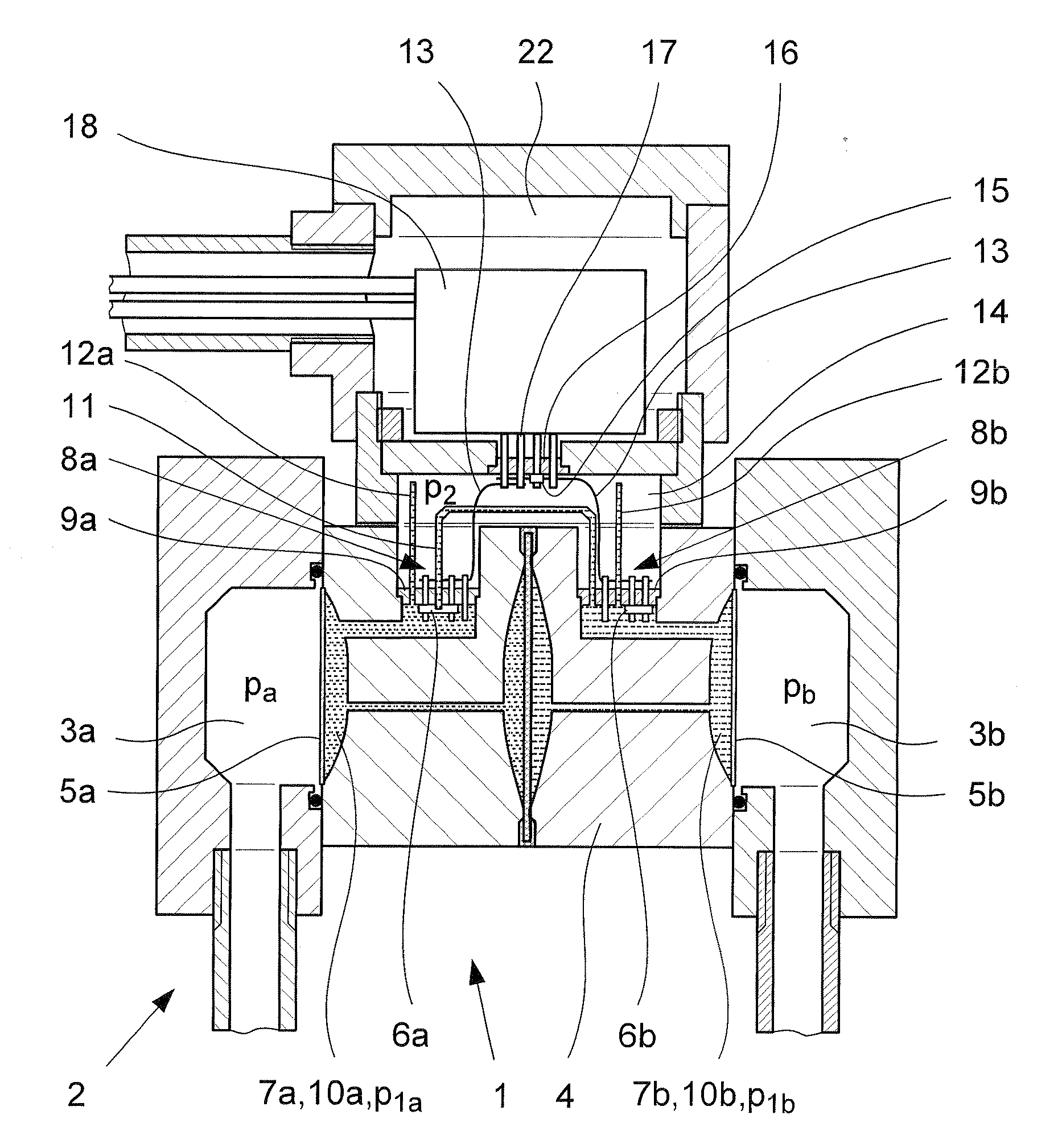
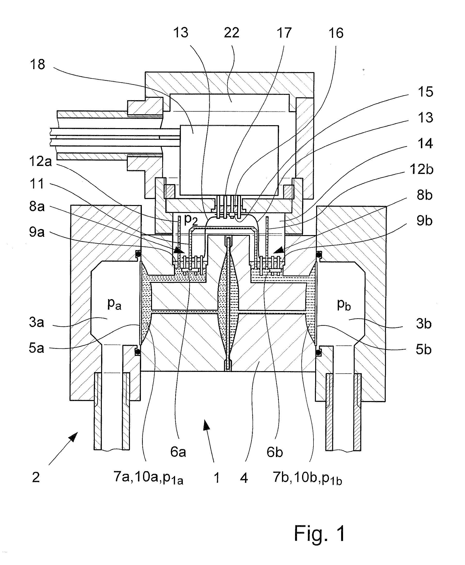
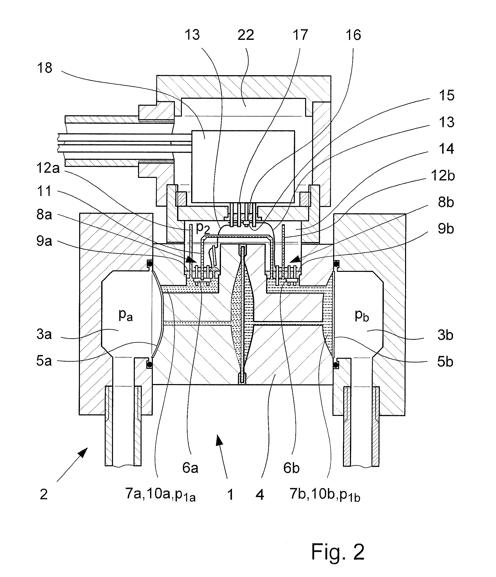
[0034]In FIGS. 1 to 7, a pressure transducer 1 is shown in connection with a complete pressure sensor which happens to be a combined absolute and difference pressure sensor. The pressure transducer 1 serves the purpose of determining at least one pressure pa, pb in a process media 3a, 3b. The pressure transducer 1 has a housing 4 with a separating diaphragm 5a, 5b, a first pressure-sensing element 6a, 6b, a contact media 7a, 7b, multiple connection elements 8a, 8b and a first seal 9a, 9b. Since the described pressure transducer 1—by all means, also—is a matter of a difference pressure transducer, practically all of the structures coupled with measurement exist twice, which, however, does not change the fact that the described and shown pressure transducer 1 as well as the described and shown pressure sensor 2 and the method described using the figures can be realized just as easily as with a simple (absolute) pressure sensor.

[0035]The separating diaphragm 5a, 5b at hand is of Hallst...


PUM


Abstract

A pressure transducer for a pressure sensor (2) for determining at least one pressure (pa, pb) in a process media (3a, 3b) has a housing (4) with a separating diaphragm (5a, 5b), at least one first pressure-sensing element (6a, 6b), a contact media (7a, 7b), at least one first connection element (8a, 8b) and at least one first seal (9a, 9b). The separating diaphragm (5a, 5b) separates the process media (3a, 3b) from the contact media (7a, 7b), the contact media (7a, 7b) conveys the pressure (pa, pb) of the process media (3a, 3b) determined by the separating diaphragm (5a, 5b) to the first pressure-sensing element (6a, 6b). The first seal (9a, 9b) houses the first connection element (8a, 8b) and the housing (4), the separating diaphragm (5a, 5b) and the first seal (9a, 9b) form a first pressure chamber (10a, 10b). A second pressure chamber (14) is provided on the side of the first pressure chamber (10a, 10b) opposite the first seal (9a, 9b) and a second pressure-sensing element (15) is arranged in the second pressure chamber (14).

Description

BACKGROUND OF THE INVENTION[0001]1. Field of the Invention[0002]The invention relates to a pressure transducer for a pressure sensor for determining at least one pressure in a process media having a housing, a separating diaphragm, at least one first pressure-sensing element and at least a first seal, wherein the separating diaphragm separates the process media from the contact media, the contact media conveys the pressure of the process media determined by the separating diaphragm to the first pressure-sensing element, the first seal houses the first connection element and wherein the housing, the separating diaphragm and the first seal form a first pressure chamber. The invention relates further to a method for monitoring the state of such a pressure transducer as well as a pressure sensor that is provided with such a pressure transducer.[0003]Pressure transducers of the type being discussed here have been known for a long time and are used to transform the pressure to be determin...

Claims


Application Information

Patent Timeline
IPC IPC(8): G01L15/00
CPCG01L13/025G01L19/0672G01L19/0645G01L7/08G01L19/00G01L27/00
Inventor GALINSKY, UDO
Owner TRANSMITTER COMPONENTS
Learn More