
Vehicle control device

a technology of vehicle control and control device, which is applied in the direction of fluid couplings, gearing, instruments, etc., can solve the problems of abnormal starting of vehicles, pump not being operated, and the friction engagement element such as the clutch or brake in the drive transmission system cannot be engaged appropriately during the operation, so as to improve the drive efficiency and energy regeneration efficiency, prevent the increase in size and the increase in energy consumption of the electric pump, and improve the transmission efficiency of the rotational driving force

Active Publication Date: 2009-04-23
AISIN AW CO LTD
View PDF11 Cites 33 Cited by
  • Summary
  • Abstract
  • Description
  • Claims
  • Application Information

AI Technical Summary

Benefits of technology

[0010]In one aspect, the present invention provides a vehicle control device which is structured such that hydraulic oil discharged from an electric pump can be supplied to a lock-up engagement element of a fluid coupling to engage the lock-up engagement element, in which the occurrence of an engagement failure, the occurrence of a shock, and the like of the lock-up engagement element can be prevented while preventing increase in size and increase in energy consumption of the electric pump.
[0044]For example, in a hybrid vehicle including both of the rotating electrical machine and the engine as the drive power source, improving the transmission efficiency of the rotational driving force results in improvements to the drive efficiency and the energy regeneration efficiency by releasing the transmission clutch to separate the engine and transmitting the rotational driving force of the rotating electrical machine to the wheel to start the vehicle in the state where the lock-up engagement element is engaged. Further, as described above, it is possible to prevent the increase in size and the increase in energy consumption of the electric pump, and to prevent the occurrence of an engagement failure of the lock-up engagement element, the occurrence of a shock, and the like.

Problems solved by technology

In the case where the vehicle is started from a state where the hydraulic pressure is decreased in this manner, a friction engagement element such as a clutch or brake included in the drive transmission system cannot be engaged appropriately during a period from when the drive power source is started until the hydraulic pressure rises.
Thus, situations exist where the vehicle is started in an abnormal manner due to these friction engagement elements suddenly engaging to cause a shock or the like.
However, when the electric pump cannot be driven, such as in cases where the oil temperature of the hydraulic oil is extremely high or extremely low, the electric pump is not operated and the rotating electrical machine is driven to supply hydraulic oil using the mechanical pump.
When such vehicles are started or run at low vehicle speed, it is necessary to engage the lock-up engagement element using hydraulic pressure of the hydraulic oil discharged from the electric pump, since the discharge amount of the hydraulic oil from the mechanical pump is not sufficient.
However, since the electric pump generally has a lower discharge performance than the mechanical pump, a situation may arise in which the discharge amount of the hydraulic oil from the electric pump becomes insufficient and the necessary hydraulic pressure cannot be ensured.
On the contrary, in the case where the temperature of the hydraulic oil is extremely high, the viscosity of the hydraulic oil decreases to increase the leakage amount from respective sections of supply destinations of the hydraulic oil, and the discharge amount of the hydraulic oil from the electric pump becomes relatively insufficient.
When an attempt to engage the lock-up engagement element is made in a state where the discharge amount of the hydraulic oil from the electric pump is insufficient, there is a possibility that an engagement failure such as slippage occurs, a shock due to sudden engagement occurs, or the like.
On the other hand, when the electric pump having a high discharge performance is used to prevent such a situation, there are problems that the pump increases in size, increases in weight and volume and that energy consumption (electrical power consumption) necessary for the operation of the electric pump increases.
Accordingly, it becomes unnecessary to use the electric pump having a high discharge performance to prevent a situation in which the discharge amount of the electric pump becomes insufficient.

Method used


Image

  • Vehicle control device
  • Vehicle control device
  • Vehicle control device

Examples


first embodiment

1. First Embodiment

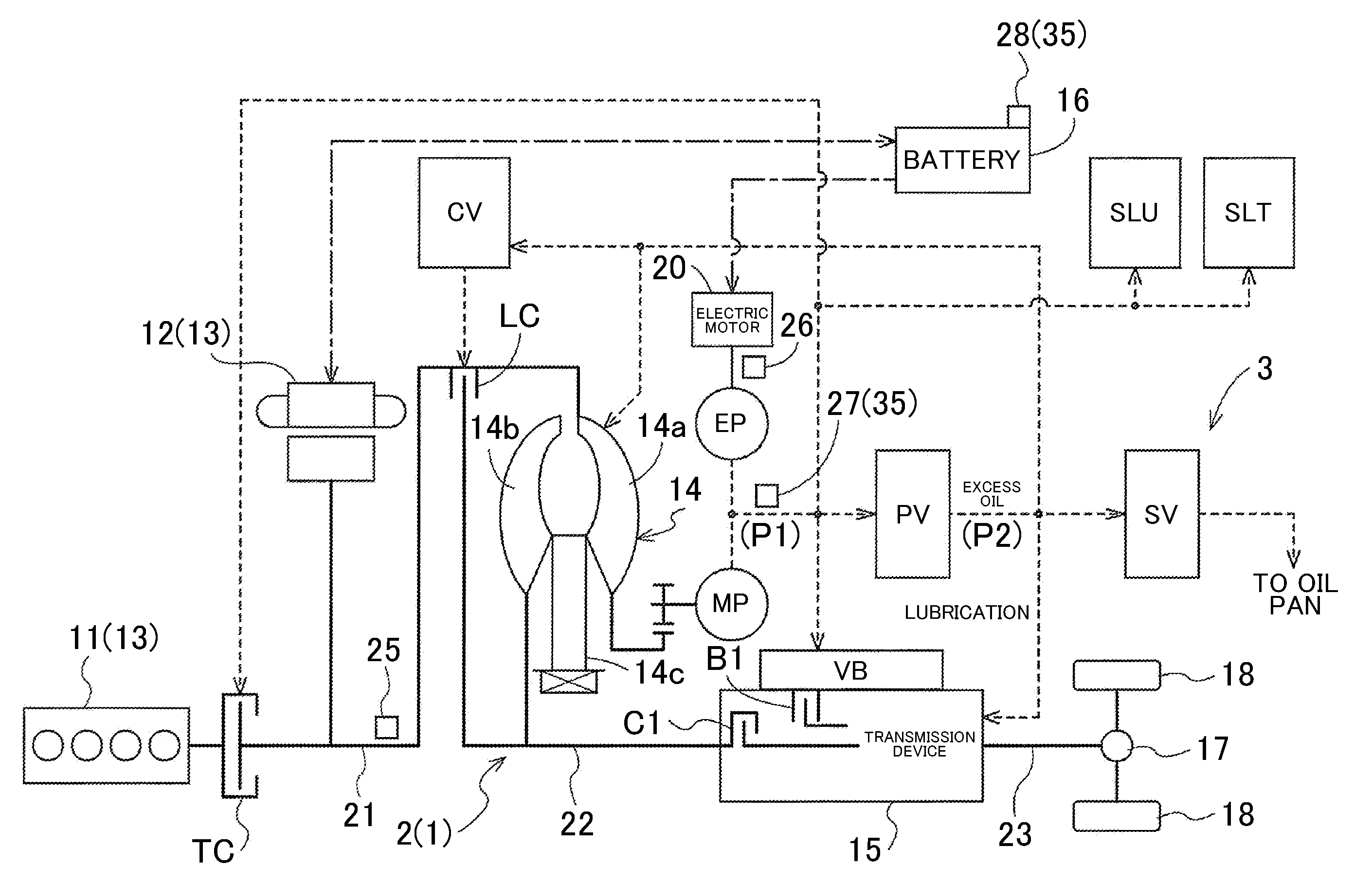
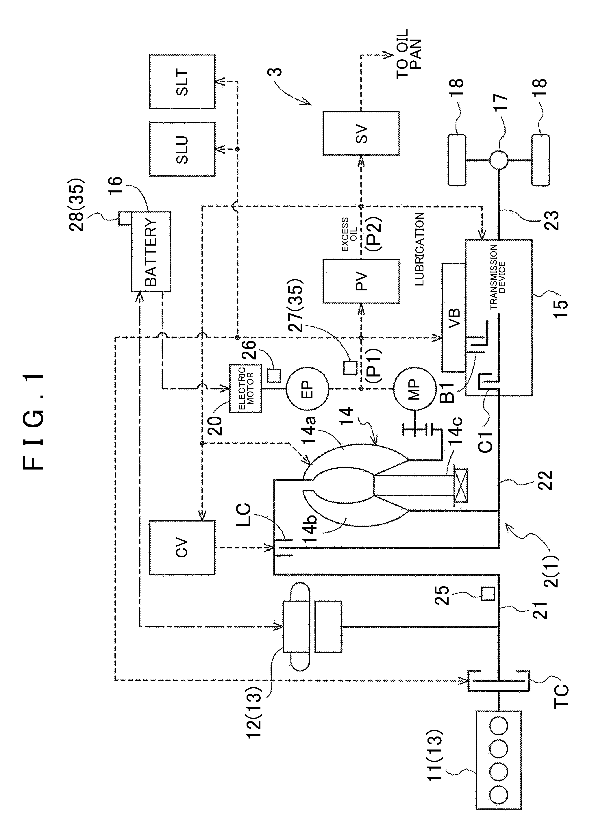
[0057]In this exemplary embodiment, a case where a vehicle control device 1 according to the present invention is applied to a vehicle drive device 2 for a hybrid vehicle will be described. FIG. 1 is a schematic diagram showing a configuration of a drive transmission system and a hydraulic pressure control system of the vehicle drive device 2 including the vehicle control device 1 according to this exemplary embodiment. In the figure, a solid line shows a transmission route of driving force, a dotted line show a supply route of hydraulic oil, and a dashed-dotted line shows a supply route of electric power. Note that (P1) or (P2) arranged near the dotted line shows that the hydraulic pressure of the hydraulic oil in the supply route is a first hydraulic pressure P1 or a second hydraulic pressure P2. As shown in FIG. 1, the vehicle drive device 2 according to this exemplary embodiment includes an engine 11 and a rotating electrical machine 12 as drive power source 1...

second embodiment

2. Second Embodiment

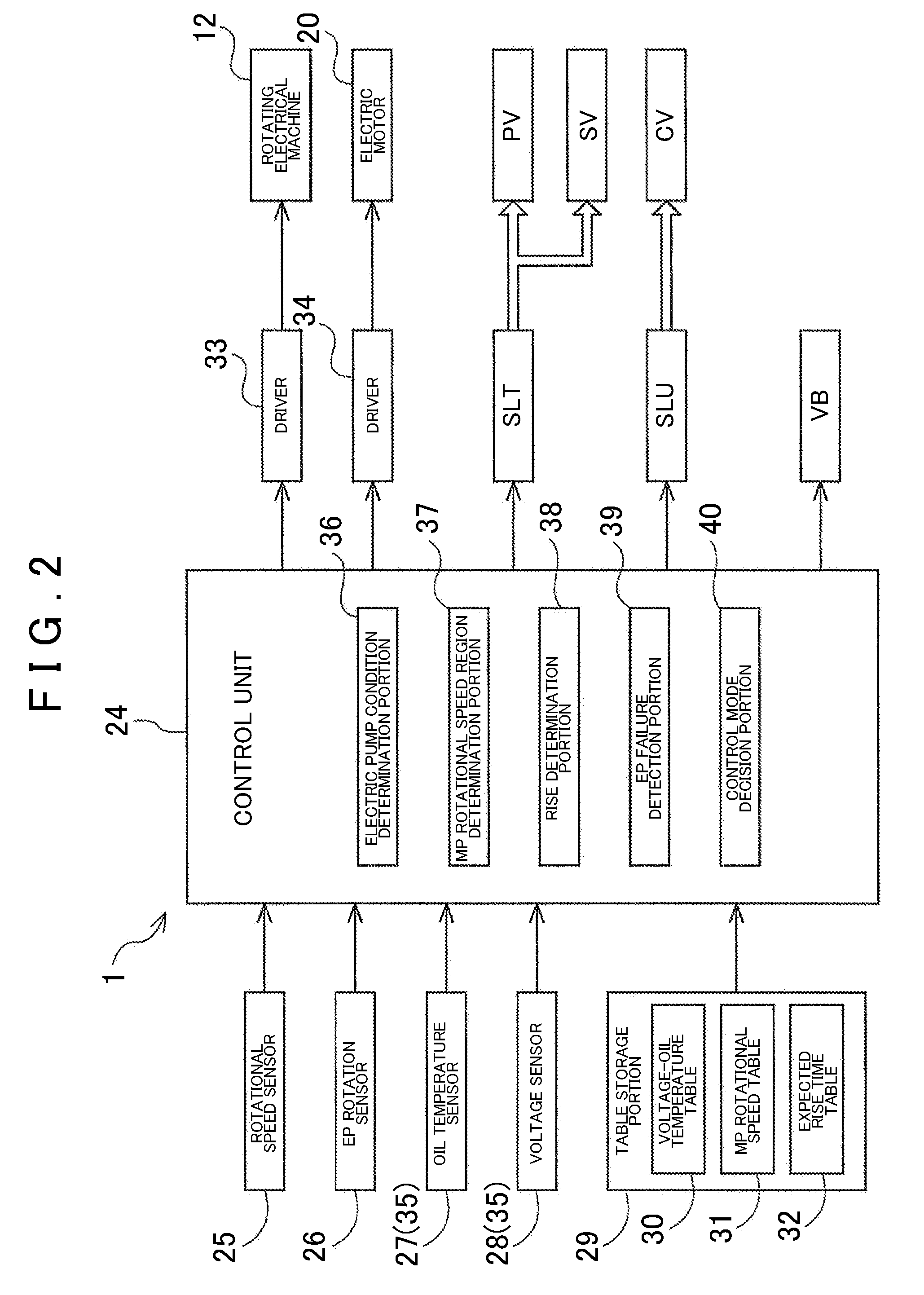
[0107]Next, a second exemplary embodiment of the present invention will be described. The vehicle drive device 2, to which the vehicle control device 1 according to this embodiment is applied, is applied in a similar manner as in the first exemplary embodiment, and the hardware configuration of the hydraulic control device 3 is also similar to that of the first exemplary embodiment. On the other hand, the vehicle control device 1 according to this exemplary embodiment differs from that of the first exemplary embodiment by the method of determining conditions R1 to R3 by the electric pump condition determination portion 36 of the control unit 24 shown in FIG. 2, and in the configuration of the table used for the determination of the conditions R1 to R3. The differences from the first exemplary embodiment will be described below. Note that the configurations of this exemplary embodiment are similar to those of the first embodiment unless otherwise stated in particu...


PUM


Abstract

A vehicle control device including an input member drive-connected to a power source; a mechanical pump; an electric pump assisting the mechanical pump; a drive mechanism transmitting the rotational driving force of the input member to an output member; a fluid coupling between the input member and the drive transmission mechanism and including a lock-up engagement element which receives hydraulic oil discharged from the mechanical pump and the electric pump to operate; a state detection unit that detects the state of the one or more factors that the discharge of the electric pump; and a control unit which executes a first or second control mode, wherein the first control mode permits engagement of the lock-up engagement element if a first condition is satisfied based on the one or more factors, and wherein a second control mode inhibits engagement of the lock-up engagement element if the first condition is not satisfied.

Description

CROSS-REFERENCE TO RELATED APPLICATIONS[0001]This Application claims priority from Japanese Patent Application No. 2007-275531 filed on Oct. 23, 2007, the disclosure of which, including the specification, drawings and abstract, is incorporated herein by reference in its entirety.BACKGROUND OF THE INVENTION[0002]1. Field of the Invention[0003]Apparatus and methods consistent with the present invention relate to a vehicle control device including an input member drive-connected to a drive power source, such as an engine or a rotating electrical machine, and may also includes a mechanical pump which operates by rotational driving force of the input member, and an electric pump which assists the mechanical pump.[0004]2. Description of the Related Art[0005]In recent years, vehicles having an idling stop function of stopping an engine when the vehicle makes a stop, hybrid vehicles including an engine and a rotating electrical machine (motor or generator) as a drive power source, electric ...

Claims


Application Information

Patent Timeline
IPC IPC(8): F16H61/14G06F17/00B60K6/48B60K6/547B60W10/02B60W10/10B60W10/30B60W20/00F16H59/68F16H59/72F16H61/02
CPCB60K6/48F16H61/0025Y02T10/6221F16H61/143F16H2045/002F16H61/0031Y02T10/62
Inventor KOBAYASHI, YASUHIKOYAMAGUCHI, YASUONOMURA, SHINICHI
Owner AISIN AW CO LTD
Learn More