
Titanium treatment to minimize fretting

a titanium alloy and titanium treatment technology, applied in the direction of solid-state diffusion coating, waterborne vessels, machines/engines, etc., can solve the problems of increased fretting fatigue, increased fretting wear, and increased fretting wear, so as to reduce the susceptibility of the surface to fretting, reduce the cost of equipment, and reduce the effect of service cost and reliability

Inactive Publication Date: 2009-04-23
GENERAL ELECTRIC CO
View PDF28 Cites 6 Cited by
  • Summary
  • Abstract
  • Description
  • Claims
  • Application Information

AI Technical Summary

Benefits of technology

The method significantly decreases fretting susceptibility, extends the lifespan of components, and reduces servicing costs by creating a hardened surface with a low coefficient of friction, maintaining effectiveness even in high-altitude and high-temperature environments.

Problems solved by technology

The titanium-to-titanium surface contact is susceptible to fretting wear and fretting fatigue.
The problem of fretting is magnified in systems having a titanium-containing surface contacting another titanium-containing surface.
For example, in a titanium compressor disk and titanium airfoil system, the fretting fatigue may result from movement of the dovetail of the airfoil within the slot in the compressor disk.
A second source of movement resulting in fretting fatigue in the dovetail system is the vibration from the airfoil.
Aerodynamic forces may result in oscillation of the airfoil within the dovetail slot.
As the airfoil vibrates, the surface of the dovetail section of the airfoil slides against the surface of the slot of the compressor disk, resulting in fretting fatigue.
However, the shot-peening process requires expensive equipment additional processing steps and may result in surfaces having variability in roughness and dimensional accuracy.
In addition, the shot-peened surface provides insufficient resistance to fretting fatigue and wear.
The reduced adhesion acts to reduce fretting fatigue and wear, but does not provide reduced adhesion throughout the operational conditions of the compressor disk / airfoil system.
The conventional lubricant coatings also eventually lead to material transfer between the surfaces.
In addition, the coated dovetail surface provides insufficient resistance to fretting fatigue and wear.
High temperature carburization methods suffer from the drawback that the method requires expensive, specialized equipment, capable of operating under high temperatures.
Thermal treatments of blade dovetails and disks preclude use of conventional carburizing practices.

Method used


Image

  • Titanium treatment to minimize fretting
  • Titanium treatment to minimize fretting
  • Titanium treatment to minimize fretting

Examples


Embodiment Construction

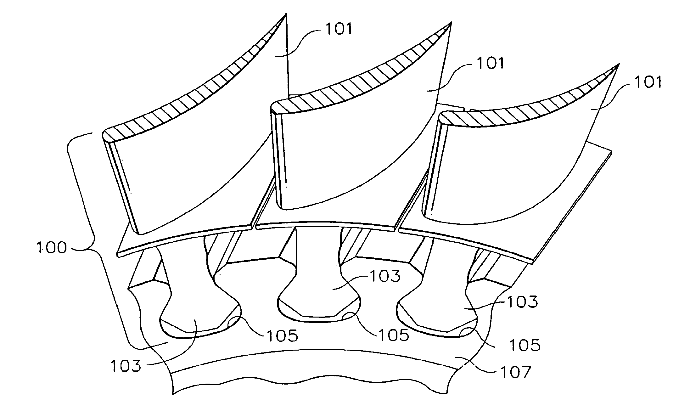
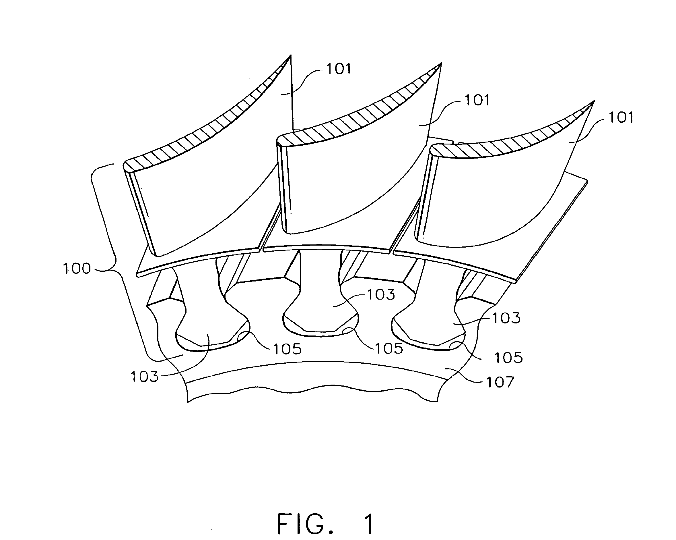
[0029]FIG. 1 is a cutaway view of a section of a high-pressure compressor for a turbine engine according to the present invention. The compressor includes a plurality of blades 100. The blades 100 include an airfoil 101 and a dovetail 103, which is positioned within dovetail slots 105 in a compressor disk 107. The dovetail 103 of the blade 100 retains the blade 100 during operation of the gas turbine engine. The blade 100 and the compressor disk 107 according to the invention include titanium and have one or more surfaces that are in frictional contact that are carburized to produce a surface having a carburized zone 401 (see FIGS. 4-9). In addition, one or more of the surfaces of the dovetail 103 and dovetails slots 105 of the compressor disk 107 are coated with a lubricant coating 601 (see FIGS. 6-9).

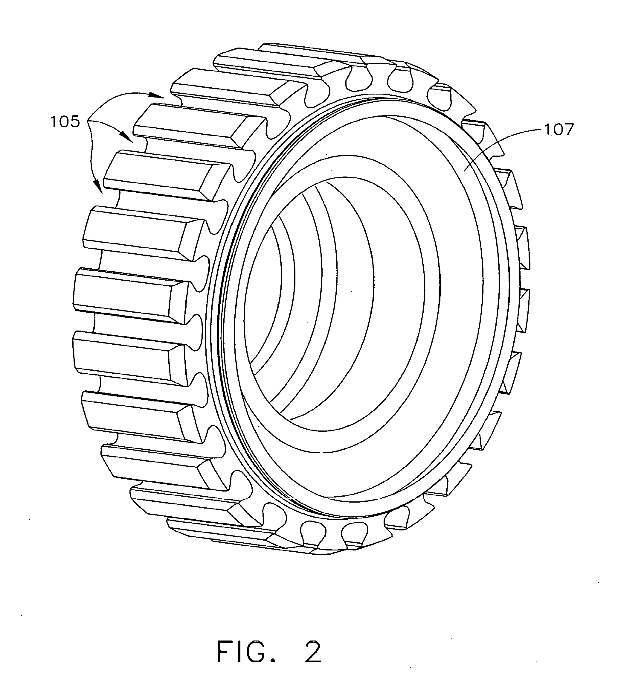
[0030]FIG. 2 shows a perspective view of a compressor disk 107 according to an embodiment of the present invention, wherein FIG. 2 shows dovetail slots 105 into which the dovetail 103...


PUM

PropertyMeasurementUnit
temperaturesaaaaaaaaaa
temperatureaaaaaaaaaa
weight percentaaaaaaaaaa

Abstract

A method for surface treating a titanium gas turbine engine component. The method includes providing a gas turbine engine component having a titanium-containing surface. The component is heated to a temperature sufficient to diffuse carbon into the titanium and below 1000° F. The surface is contacted with a carbon-containing gas to diffuse carbon into the surface to form carbides. Thereafter, the carbide-containing surface is coated with a lubricant comprising a binder and a friction modifier. The binder preferably including titanium oxide and the friction modifier preferably including tungsten disulfide. The coefficient of friction between the surface and another titanium-containing surface is less than about 0.6 in high altitude atmospheres.

Description

CROSS-REFERENCE TO RELATED APPLICATIONS[0001]This application is a divisional of U.S. application Ser. No. 11 / 247,686, filed Oct. 11, 2005, which is incorporated by reference in its entirety and which claims the benefit of U.S. Provisional Application No. 60 / 694,759, filed Jun. 28, 2005.FIELD OF THE INVENTION[0002]The present invention is directed to a method for surface treating titanium and titanium alloys. In particular, the invention is drawn to surface treating gas turbine engine components.BACKGROUND OF THE INVENTION[0003]A gas turbine engine generally operates by pressurizing air in a compressor and mixing the air with fuel in a combustor. The air / fuel mixture is ignited and hot combustion gasses result, which flow downstream through a turbine section. The compressor typically includes compressor disks having airfoils dovetailed into the compressor disk. The compressor may include multiple disks, each having a plurality of airfoils.[0004]Each of the compressor disk and the ai...

Claims


Application Information

Patent Timeline
Patent Type & Authority Applications(United States)
IPC IPC(8): F01D5/14F01D5/02F01D5/28F01D5/30C22C19/03
CPCC23C8/20C23C8/80Y10T29/49337Y10T29/49336Y10T29/4932Y10T29/49746Y10T29/49339Y10T29/49229
Inventor BRUCE, ROBERT WILLIAM
Owner GENERAL ELECTRIC CO
Learn More