
Broadband light source unit and optical analyzer

a light source unit and optical analyzer technology, applied in the direction of optical radiation measurement, instruments, lighting and heating apparatus, etc., can solve the problems of noise-like lasers not only limited in their applications, but also disadvantageous in cost and reproducibility as a product, and cannot achieve flat spectral forms

Active Publication Date: 2009-04-16
SUMITOMO ELECTRIC IND LTD
View PDF1 Cites 13 Cited by
  • Summary
  • Abstract
  • Description
  • Claims
  • Application Information

AI Technical Summary

Benefits of technology

The present invention offers a broadband light source unit that produces a supercontinuum lightwave with a flat spectral form using a simple system. The unit includes a light source, conversion means, and a nonlinear optical medium section. The conversion means produces a second source lightwave with pulses having different intensities, which is combined with the first source lightwave to create the supercontinuum lightwave. The nonlinear optical medium section produces the supercontinuum lightwave by using a nonlinear optical phenomenon. The invention also provides an optical analyzer with the broadband light source unit and a light-applying section for applying the supercontinuum lightwave to a measurement-undergoing object and an image pickup section for picking up an image of the object.

Problems solved by technology

However, the SC lightwave has a problem in that it sometimes cannot achieve a flat spectral form.
Nevertheless, the noise-like laser is not only limited in its applications but also disadvantageous both in cost and in reproducibility as a product.

Method used


Image

  • Broadband light source unit and optical analyzer
  • Broadband light source unit and optical analyzer
  • Broadband light source unit and optical analyzer

Examples


first embodiment

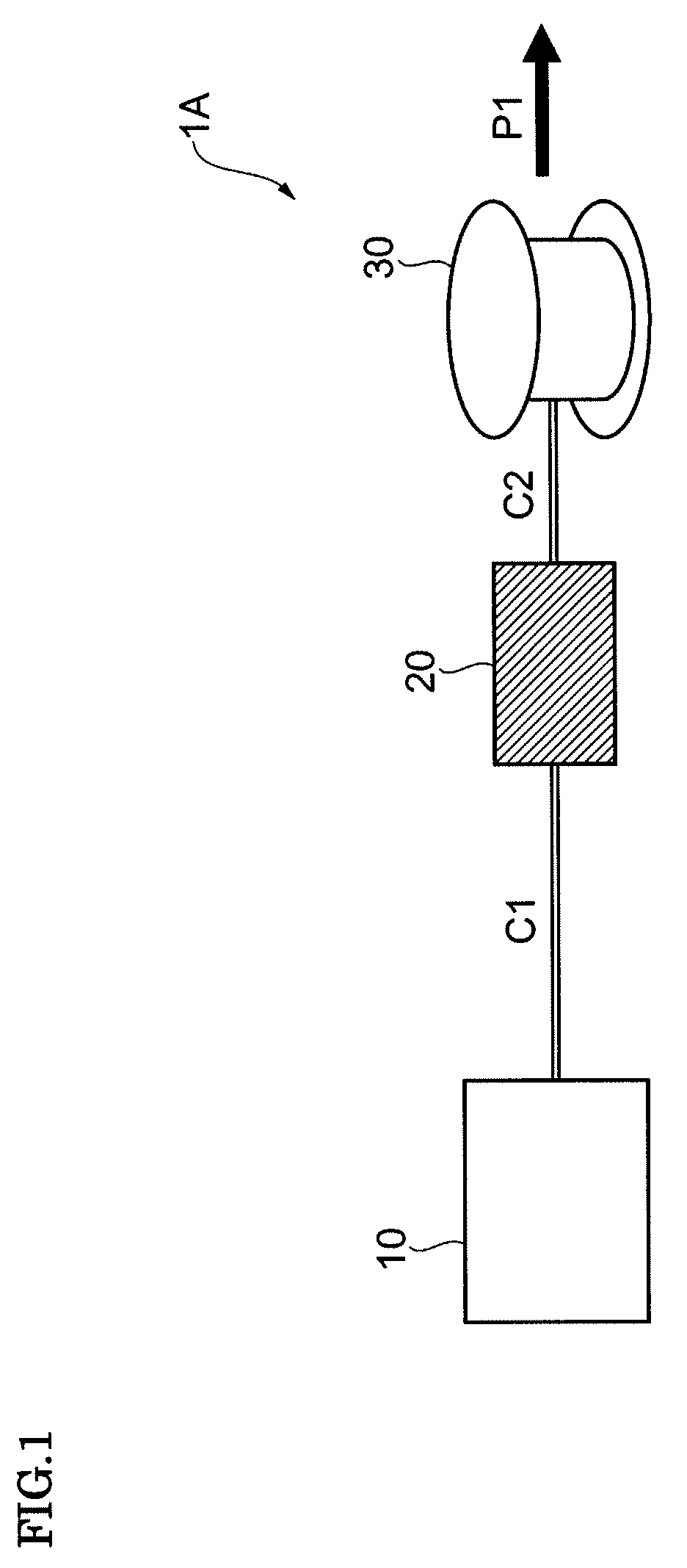
[0027]FIG. 1 is a schematic diagram showing a broadband light source unit 1A, which is a first embodiment of the present invention. The broadband light source unit 1A is provided with a light source 10, a conversion means (an intensity modulator 20), and an optical fiber 30. The light source 10 outputs a pulse lightwave C1 (a first source lightwave) as a source lightwave.

[0028]the intensity modulator 20 is, for example, a gain-variable amplifier or an attenuation-variable attenuator. FIGS. 2A, 2B, and 2C are graphs respectively showing the pulse lightwave C1 before the conversion, the voltage of the modulation signal, and a pulse lightwave C2 after the conversion in the intensity modulator 20 of the broadband light source unit 1A. The modulation signal has a frequency that deviates from an integral multiple and an integral submultiple both of the pulse repetition frequency. The pulse lightwave C1 has pulses that are periodic and that have a constant intensity. The individual pulses ...

second embodiment

[0032]FIG. 4 is a schematic diagram showing a broadband light source unit 1B, which is a second embodiment of the present invention. The broadband light source unit 1B is provided with a light source 10, a conversion means, and an optical fiber 30. The conversion means is composed of a first optical coupler 40, a second optical coupler 42, and N optical fibers 44 having lengths different from one another (N means the number of optical fibers).

[0033]The first optical coupler 40 branches a pulse lightwave C1 outputted from the light source 10 into N branched lightwaves such that the N branched lightwaves have intensities different from one another (N means the number of branched lightwaves). The N branched lightwaves are introduced into the N optical fibers 44 individually. The N optical fibers 44 are optical waveguides that have lengths different from one another and that optically couple the first optical coupler 40 with the second optical coupler 42. The N optical fibers 44 receive...

third embodiment

[0036]FIG. 6 is a schematic diagram showing a broadband light source unit 1C, which is a third embodiment of the present invention. The broadband light source unit 1C is provided with a light source 10, a conversion means, and an optical fiber 30. The conversion means is composed of beam splitters 50, 52, 54, and 56 and mirrors 51, 53, 55, and 57. In the third embodiment, with respect to all the mirrors and beam splitters, the lightwave enters them at an entry angle of 45 degrees and is reflected from them at an angle of reflection of 45 degrees.

[0037]The beam splitter 50 transmits part of a pulse lightwave C1 outputted from the light source 10 to send it to the beam splitter 56 and reflects the remainder to send it to the mirror 51. The mirror 51 receives the branched lightwave reflected from the beam splitter 50 and reflects it to send it to the beam splitter 52. The beam splitter 52 receives the branched lightwave reflected from the mirror 51, transmits part of the branched light...


PUM

PropertyMeasurementUnit
entry angleaaaaaaaaaa
wavelength bandaaaaaaaaaa
lengthsaaaaaaaaaa

Abstract

The invention offers a broadband light source unit that produces using a simple system a supercontinuum lightwave having a flat spectral form and an optical analyzer using the unit. The broadband light source unit has a light source that outputs a first source lightwave, which is a pulse lightwave having periodic pulses with a constant intensity, a conversion means that receives the first source lightwave, produces a second source lightwave having pulses whose intensities are different from one another, and outputs it, and a nonlinear optical medium section that receives the second source lightwave, produces a supercontinuum lightwave having a wavelength band broadened through a nonlinear optical phenomenon, and outputs it. The optical analyzer has the foregoing broadband light source unit, a light-applying section that applies a supercontinuum lightwave outputted from the broadband light source unit to a light-receiving region of a measurement-undergoing object, and an image pickup section that receives a lightwave generated at the light-receiving region by the application of the supercontinuum lightwave and picks up an image of the measurement-undergoing object.

Description

BACKGROUND OF THE INVENTION[0001]1. Field of the Invention[0002]The present invention relates to a broadband light source unit and an optical analyzer incorporating the unit.[0003]2. Description of the Related Background Art[0004]A supercontinuum lightwave (SC lightwave), which is a type of broadband lightwaves, can be obtained by passing a pulse lightwave having a narrow spectral width, or the like, through a nonlinear optical medium. The lightwave broadens its spectral width through undergoing dispersion and a nonlinear optical effect in the nonlinear optical medium. Usually, the spectral width of the SC lightwave is broadened to the extent of 10 to 100 times the spectral width of the inputted pulse lightwave. The SC lightwave combines the characteristics of a white lightwave and a laser lightwave and can be produced using a relatively simple method. Consequently, the SC lightwave attracts attention as a multiwavelength light source for optical communication and as an illuminating...

Claims


Application Information

Patent Timeline
Patent Type & Authority Applications(United States)
IPC IPC(8): F21V9/14F21V9/00G02F1/01
CPCG02F1/365G02F2201/205G02F2201/20G02F2001/3528G02F1/3528
Inventor TANAKA, MASATO
Owner SUMITOMO ELECTRIC IND LTD
Learn More