Method and device for triggering a circuit arrangement with electric actuators
- Summary
- Abstract
- Description
- Claims
- Application Information
AI Technical Summary
Benefits of technology
Problems solved by technology
Method used
Image
Examples
Embodiment Construction
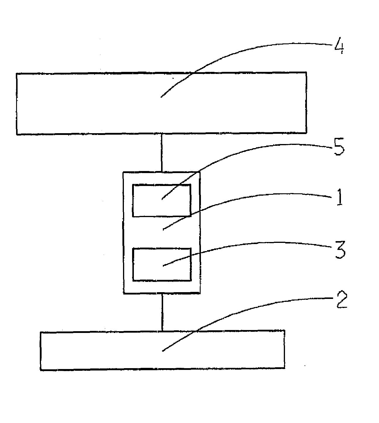
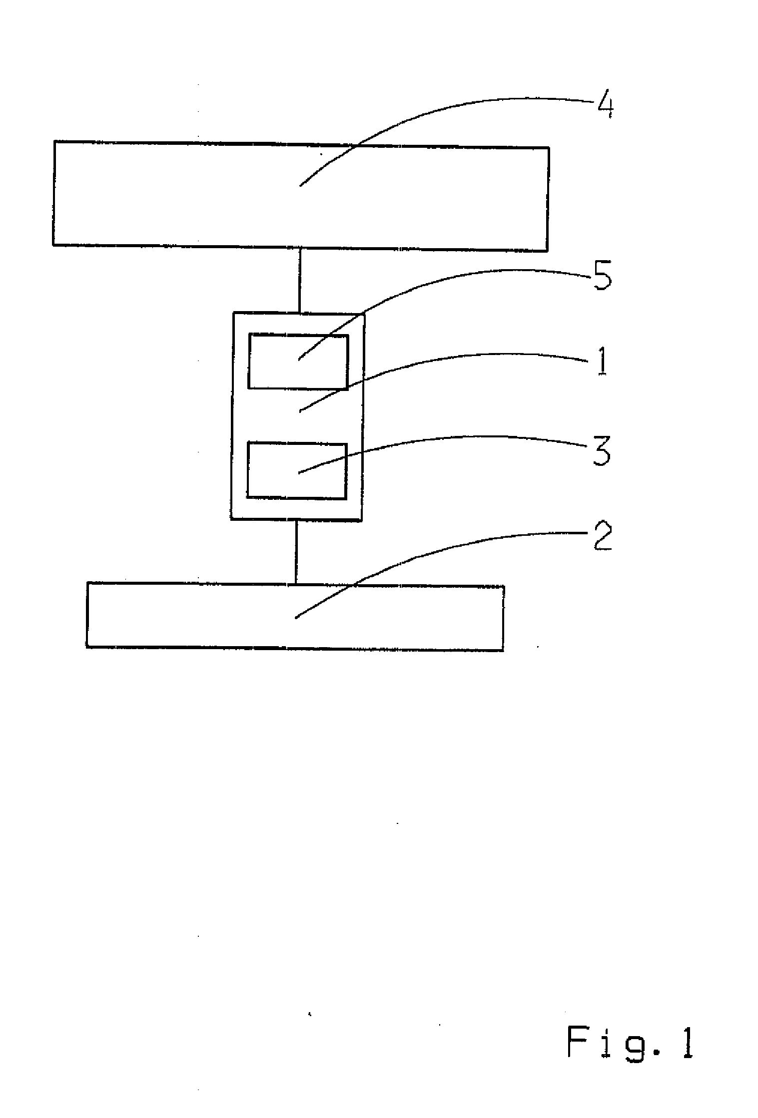
[0033]A simplified block diagram of an electronic transmission control of a motor vehicle is accordingly shown in FIG. 1. A central transmission control unit 1 with a connected hydraulic circuit 5 with directional control electromagnetic valves (not shown) is provided therein. The transmission control unit 1 communicates with an engine control and a signal detection unit 2, over which data concerning a driver request and / or a driving situation can be detected.
[0034]The transmission control unit 1 also has a processor unit 3 in which electric current and voltage data can be detected and processed in a time-resolved manner by way of suitable software, whereby a current monitoring function is made available. Via output data of the transmission control unit 1, the shift elements of the hydraulic circuit 5 can be actuated which, in turn, control a transmission and / or clutch arrangement 4.
[0035]In an electronic transmission control, a driver request is converted into signals, for example,...
PUM
 Abstract
Description
Claims
Application Information
 - R&D
- Intellectual Property
- Life Sciences
- Materials
- Tech Scout
- Unparalleled Data Quality
- Higher Quality Content
- 60% Fewer Hallucinations
Browse by: Latest US Patents, China's latest patents, Technical Efficacy Thesaurus, Application Domain, Technology Topic, Popular Technical Reports.
© 2025 PatSnap. All rights reserved.Legal|Privacy policy|Modern Slavery Act Transparency Statement|Sitemap|About US| Contact US: help@patsnap.com


