
Method and device for triggering a circuit arrangement with electric actuators

a technology of electric actuators and circuits, applied in mechanical devices, instruments, transportation and packaging, etc., can solve the problems of only observing proportional magnets in isolation, unallowably high current load during electric circuit operation, and impairing the reliability of the affected system, so as to prevent the excess of the allowed current load in the shifting arrangement

Inactive Publication Date: 2012-08-14
ZF FRIEDRICHSHAFEN AG
View PDF43 Cites 2 Cited by
  • Summary
  • Abstract
  • Description
  • Claims
  • Application Information

AI Technical Summary

Benefits of technology

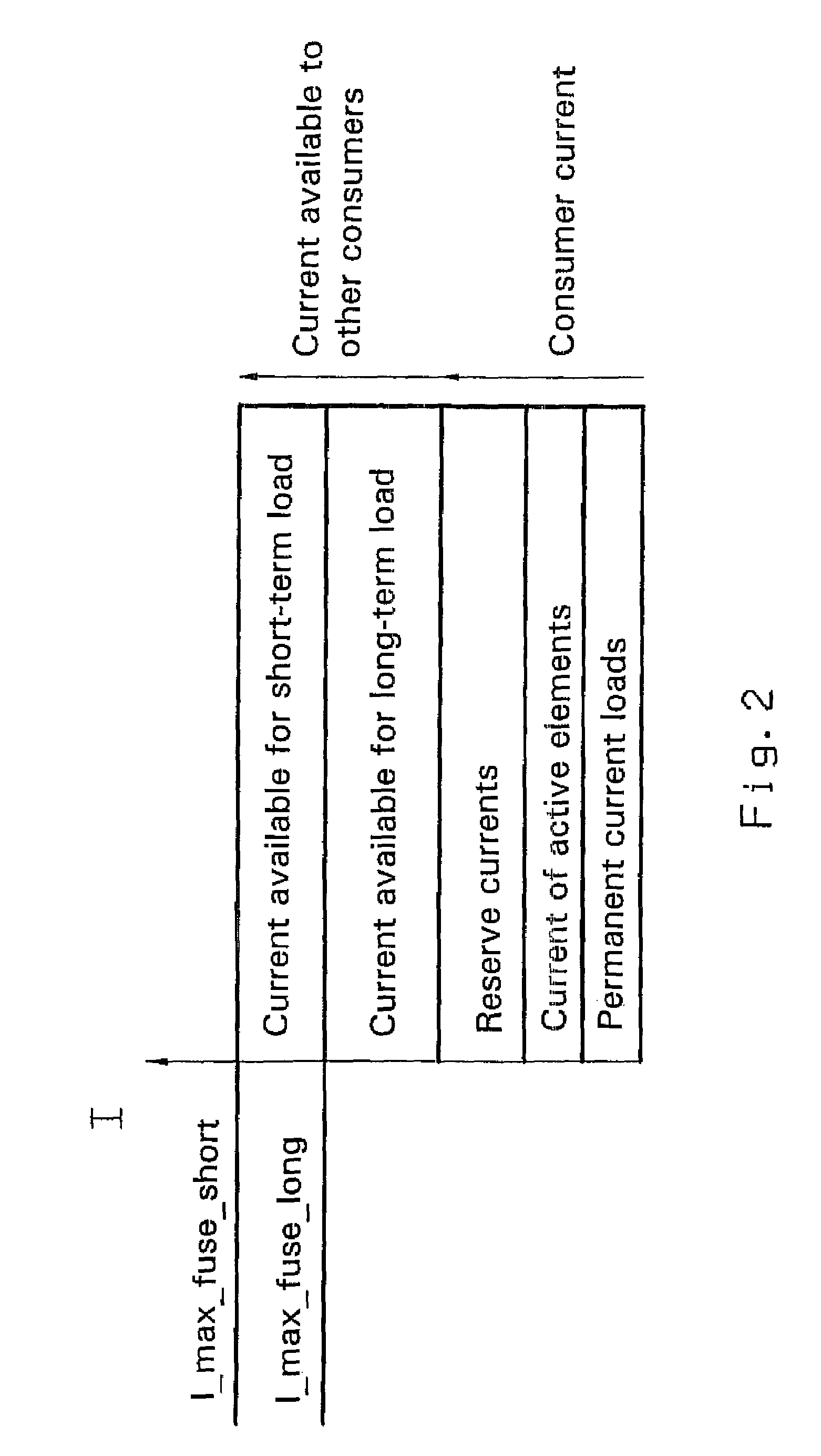
The invention is a device for actuating a shifting arrangement in a vehicle transmission control using electric actuators. It includes a current monitoring function that limits the current load in the shifting arrangement to prevent exceeding the available current. The current monitoring function determines the total current of the shifting arrangement, detects shift requests from shift elements, and prioritizes the shift requests based on their function and type. The device also includes a learning algorithm to determine the maximum allowed current load and can reliably prevent the preset allowed current load from being exceeded. The invention allows for the use of high current consumption consumers in transmission controls while preventing the risk of exceeding the preset maximum current load.

Problems solved by technology

However, since they work according to the differential pressure principle, they require a constant specific minimum operating pressure.
This can have as a consequence an unallowably high current load during operation in electric circuits with limited current supply.
A disadvantage of the known processes and devices for actuating proportional magnets is that, even though they control the actuation of individual proportional magnets, the proportional magnets are only viewed in isolation.
This can impair the reliability of the affected system in a shifting arrangement with a limited total available current, as is common in motor vehicle electric circuits.

Method used


Image

  • Method and device for triggering a circuit arrangement with electric actuators
  • Method and device for triggering a circuit arrangement with electric actuators
  • Method and device for triggering a circuit arrangement with electric actuators

Examples


Embodiment Construction

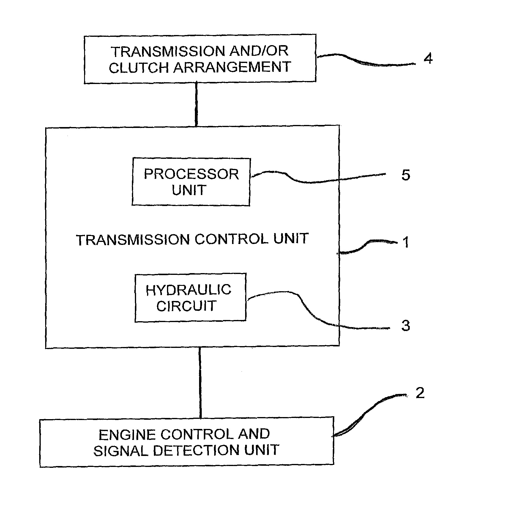
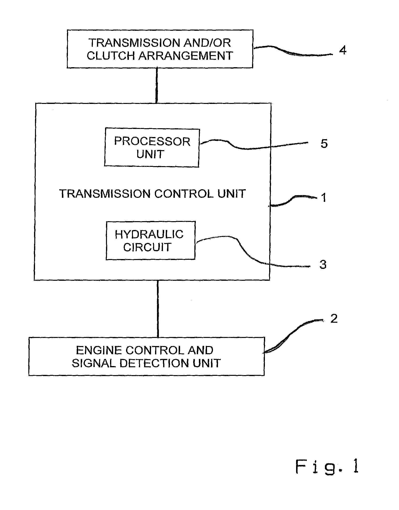
[0033]A simplified block diagram of an electronic transmission control of a motor vehicle is accordingly shown in FIG. 1. A central transmission control unit 1 with a connected hydraulic circuit 5 with directional control electromagnetic valves (not shown) is provided therein. The transmission control unit 1 communicates with an engine control and a signal detection unit 2, over which data concerning a driver request and / or a driving situation can be detected.

[0034]The transmission control unit 1 also has a processor unit 3 in which electric current and voltage data can be detected and processed in a time-resolved manner by way of suitable software, whereby a current monitoring function is made available. Via output data of the transmission control unit 1, the shift elements of the hydraulic circuit 5 can be actuated which, in turn, control a transmission and / or clutch arrangement 4.

[0035]In an electronic transmission control, a driver request is converted into signals, for example,...


PUM


Abstract

A method and device for actuating a shifting arrangement with electric actuators of a transmission control of a motor vehicle. The method includes determining a total current of the shifting arrangement available at a point in time, detecting shift requests of shift elements and compared these with the total available current. Shift requests are then tested according to preset priorities and the sequentially performed according to the priority test. The method avoids exceeding a preset allowed current load, when the requested shifts would exceed the total available current. If the total available current would not be exceeded by the requested shifts, the requests are carried out. A device is also provided in the shifting arrangement which has control and detection mechanisms that monitor current and control the current flow.

Description

[0001]This application is a national stage completion of PCT / EP2007 / 051677 filed Feb. 21, 2007, which claims priority from German Application Serial No. 10 2006 011 805.7 filed Mar. 15, 2006.FIELD OF THE INVENTION[0002]The invention concerns a process and a device for actuating a shifting arrangement with electric actuators.BACKGROUND OF THE INVENTION[0003]Electrically operable actuators, for example valves, are used in motor vehicles, in particular, for control functions in hydraulic circuits. There are basically two different types of designs. In the commonly utilized pilot operated valves, a magnet in a pilot operated system acts on a relief bore, which equalizes the pressure difference between the pressurized sides of a sealing element, wherein the sealing element on the valve seat is activated by the pressure medium itself. Magnetic valves of this kind have the advantage that they can control large flow volumes at high pressures with relatively low force and accordingly low cur...

Claims


Application Information

Patent Timeline
Patent Type & Authority Patents(United States)
IPC IPC(8): B60R16/02G06F17/00
CPCH02J1/14H02J13/0003Y10T74/19251Y10T477/677Y10T477/675Y10T477/688H02J13/00002Y02E60/00Y04S10/30
Inventor INGENBLEEK, ROBERTULBRICHT, MARKUSSTEINBORN, MARIOBRENTEL, ARMIN
Owner ZF FRIEDRICHSHAFEN AG
Learn More