Surface light source system and light source unit

a light source system and surface technology, applied in the field of surface light source systems and light source units, can solve the problems of insufficient optical efficiency, insufficient collection of light by the surface light source system, and insufficient cost of use, so as to reduce the cost of use, reduce production costs, and increase energy efficiency.

Active Publication Date: 2009-04-09
DAI NIPPON PRINTING CO LTD
View PDF16 Cites 32 Cited by
  • Summary
  • Abstract
  • Description
  • Claims
  • Application Information

AI Technical Summary

Benefits of technology

[0009]In the light of the above-described problems in the prior art, the present invention was accomplished. An object of the present invention is to provide a surface light source system capable of emitting light without non-uniformity of luminance and that of color. Another object of the present invention is to provide a surface light source system improved in the efficiency of utilization of light emitted from emission sources, and a light source unit (a set of emission sources, light source part) to be incorporated in the surface light source system. A further object of the present invention is to provide a surface light source system excellent in heat radiation characteristics, and a light source unit (a set of emission sources, light source part) to be incorporated in the surface light source system.
[0010]A first surface light source system according to the present invention comprises: a first lenticular lens sheet having multiple unit lenses, each of the unit lenses projecting on the light-exiting side; a second lenticular lens sheet having multiple unit lenses, each of the unit lenses projecting on the light-exiting side; and a light source unit having emission sources, the emission sources being capable of being divided into two types or more according to wavelength ranges of light they emit, wherein the unit lenses in the first lenticular lens sheet are arranged in one direction parallel to a sheet plane of the first lenticular lens sheet at approximately regular intervals, wherein the unit lenses in the second lenticular lens sheet are arranged in other direction at approximately regular intervals, the other direction being parallel to a sheet plane of the second lenticular lens sheet and being perpendicular to the one direction, wherein the emission sources are arranged on a plane parallel to the sheet plane of the first lenticular lens sheet, wherein emission sources of each type are arranged in the one direction at approximately regular intervals, and wherein intervals at which respective emission sources of two types or more arranged in the one direction are nearly the same in length. According to such a surface light source system, the lenticular lens sheets can effectively prevent the surface of the system from becoming non-uniform in luminance and in color in at least one direction. The emission sources may substantially be point light sources. Light emitting diodes can be used as point light sources.

Problems solved by technology

However, such a surface light source system is sometimes insufficient in the property of collecting light emitted from the emission sources, although the surface light source system includes many optical sheets.
However, even if the LCD panel is so improved, optical efficiency cannot be satisfactorily increased, and, moreover, the structure of the LCD panel is complicated, so that the cost for producing a liquid crystal display increases.
Further, of the surface of the LCD panel that faces the surface light source system of direct type, those portions that are close to the emission sources (cold cathode fluorescent tubes) and those portions that are apart from the emission sources (i.e., those portions that face the parts between two adjacent emission sources) are different in light intensity (luminance), so that the surface of the LCD panel tends to have non-uniformity of light intensity (non-uniformity of luminance).
Point light sources arranged on a plane produce two-dimensionally non-uniform luminance.
When emission sources that are different in the wavelength range of light they emit are used, the non-uniformity of color is brought about in addition to the non-uniformity of luminance.
A greater distance between the emission sources and the LCD panel, however, brings about another problem that the display has an increased thickness.
These techniques, however, cause the problem that the efficiency of utilization of the light emitted from the emission sources decreases.
This technique also causes the problem that the efficiency of utilization of the light emitted from the emission sources decreases.
The glass epoxy resin, however, has low thermal conductivity and is poor in heat-radiating characteristics.
If the temperature of the emission sources consisting of light emitting diodes increases, there occur the problems that the light the light emitting diodes emit undergoes change in color and that the life of the light emitting diodes decreases.

Method used


Image

  • Surface light source system and light source unit
  • Surface light source system and light source unit
  • Surface light source system and light source unit

Examples


modification examples

[0139]The surface light source system 50 and the light source unit 100 according to the invention are not limited to those of the above-described embodiment, and the present invention is susceptible to various modifications.

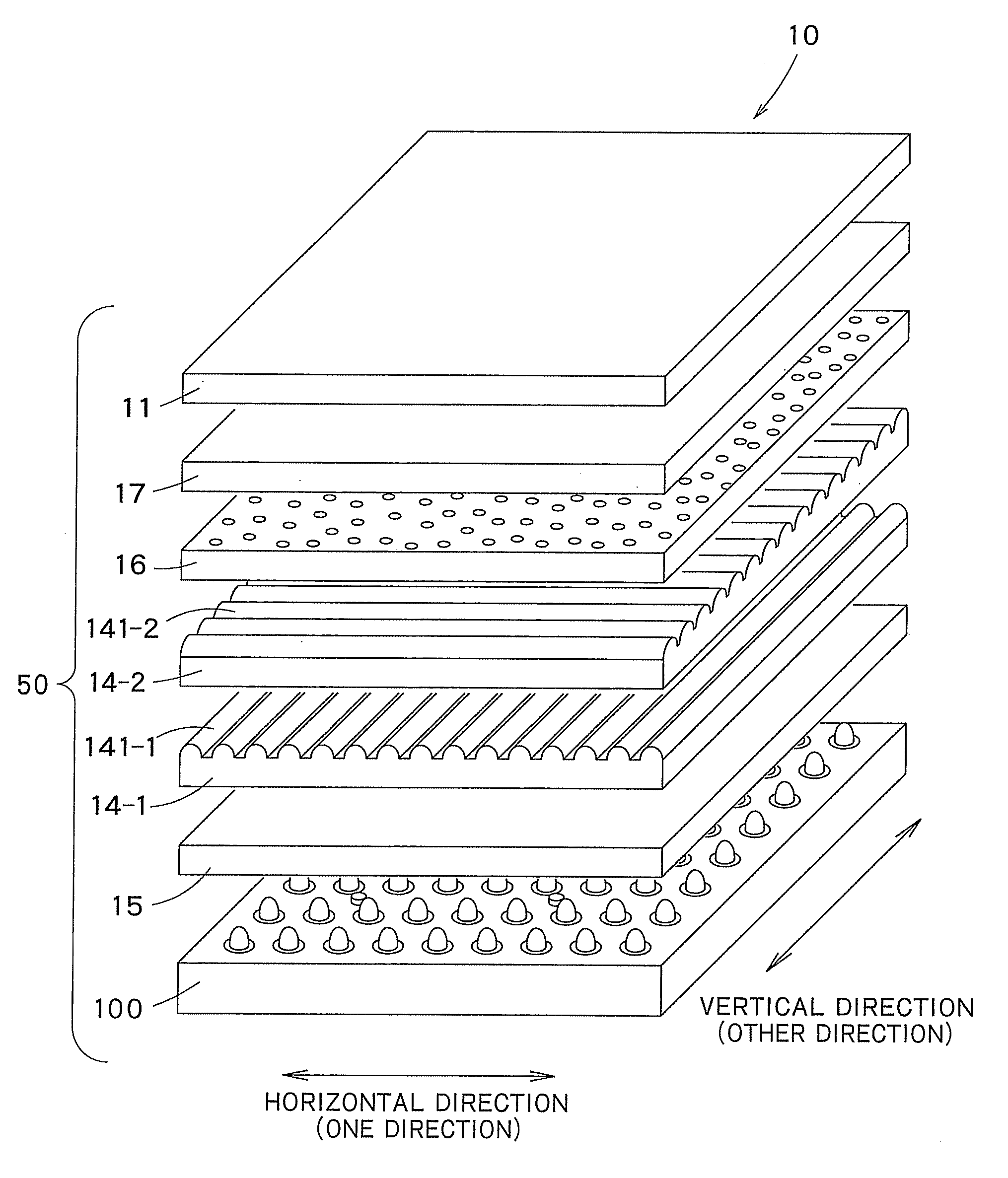
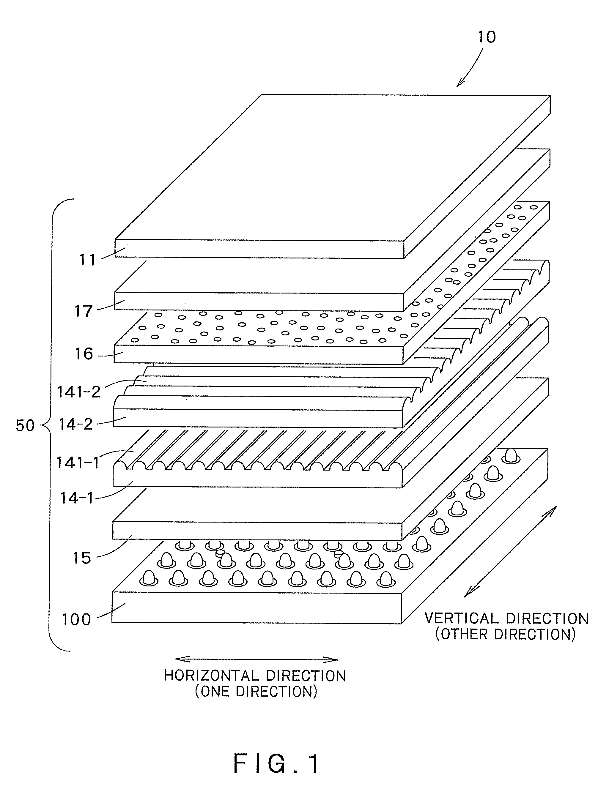
[0140](1) In the above-described embodiment, the surface light source system 50 comprises the light source unit 100, the first lenticular lens sheet 14-1, the second lenticular lens sheet 14-2, the transparent sheet 15, the diffusing sheet 16, and the reflective polarizing sheet 17. The present invention is not limited to this. Various optical sheets can be added to and / or removed from the above surface light source system; for example, the reflective polarizing sheet 17 may be removed from the surface light source system 50.

[0141](2) Further, in the above-described embodiment, the substrate layer 104 has, on its one side, the circuit layer 106 and the emission sources 101, as shown in FIG. 6. The present invention is not limited to this. The positions of the sub...


PUM


Abstract

A surface light source system 50 capable of emitting light without producing non-uniform luminance and non-uniform color distributions is provided. The surface light source system 50 comprises a lenticular lens sheet 14-1 having unit lenses 141-1 with convexity on the light-exiting side, and a light source unit 100 having emission sources 101 of two types or more that are different in the wavelength range of light they emit. The unit lenses are arranged in one direction at approximately regular intervals. Emission sources of each type are arranged in the one direction at approximately regular intervals. The intervals at which the respective emission sources of two types or more arranged in the one direction are nearly the same in length.

Description

TECHNICAL FIELD[0001]The present invention relates to a surface light source system to be used for illuminating a liquid crystal display or the like, and a light source unit to be incorporated in the surface light source system.BACKGROUND ART[0002]Surface light source systems of various types, useful for illuminating transmission type liquid crystal displays and so on, have been proposed and put to practical use. Of the surface light source systems practically used now, some systems, such as those of edge light type or of direct type, use emission sources that do not emit light two-dimensionally or that do not emit light in a sheet formation.[0003]In a surface light source system of direct type, emission sources that emit light linearly are arranged in parallel with each other, for example. In this surface light source system, cold cathode fluorescent tubes and a transmission type display element, such as an LCD (Liquid Crystal Display) panel, are spaced, as needed. Between the cold...

Claims


Application Information

Patent Timeline
IPC IPC(8): G02F1/13357
CPCG02F1/133606G02F1/133603G02F1/1335
Inventor GOTO, MASAHIRO
Owner DAI NIPPON PRINTING CO LTD
Why Eureka
Try Eureka