Injection control system
- Summary
- Abstract
- Description
- Claims
- Application Information
AI Technical Summary
Benefits of technology
Problems solved by technology
Method used
Image
Examples
Embodiment Construction
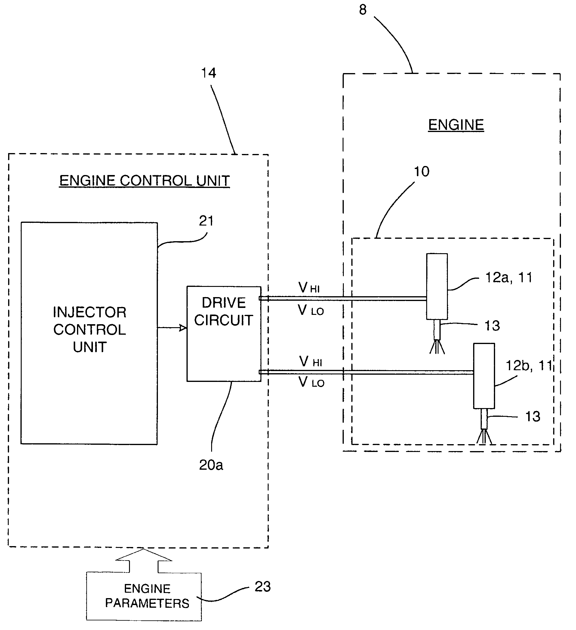
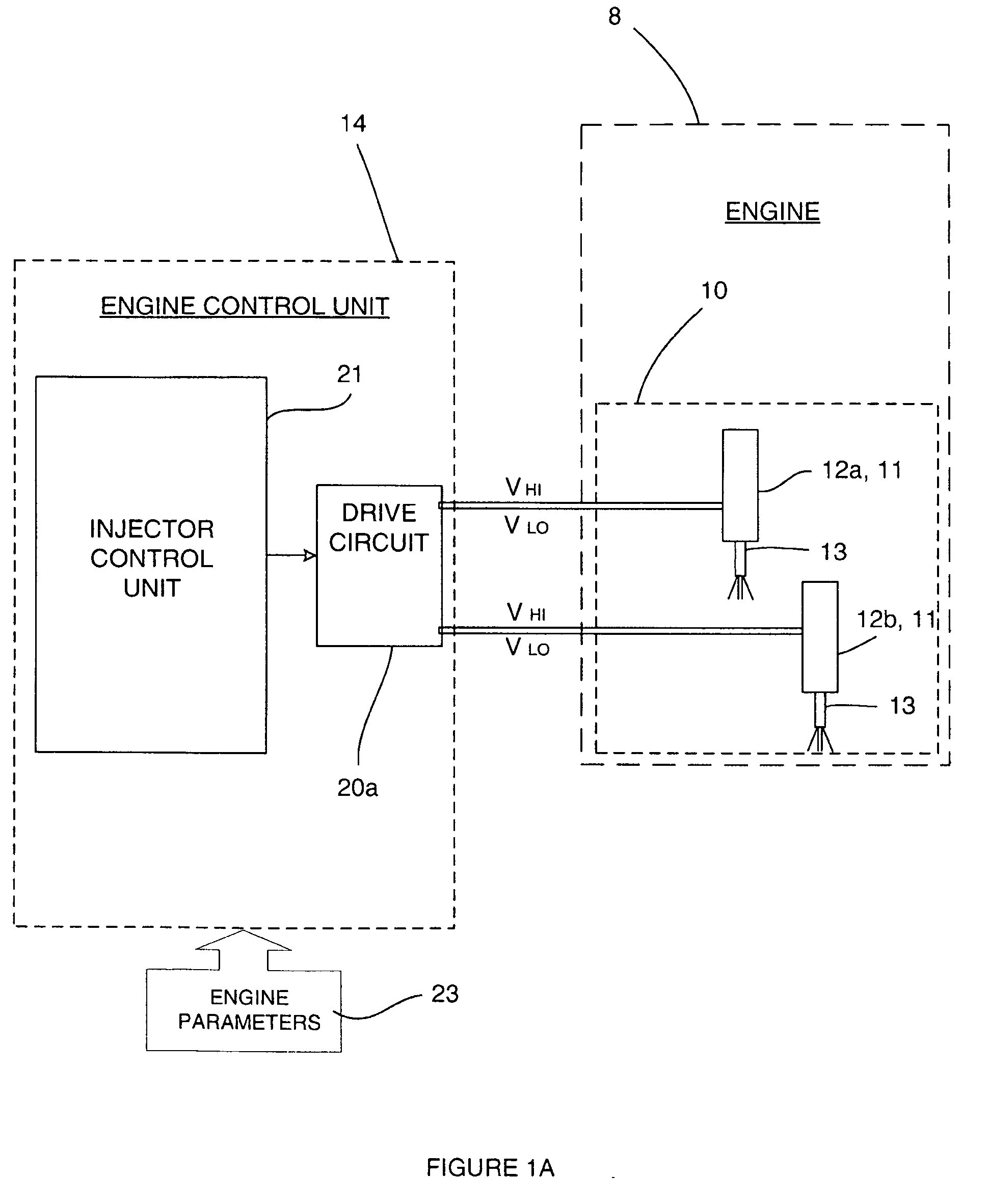
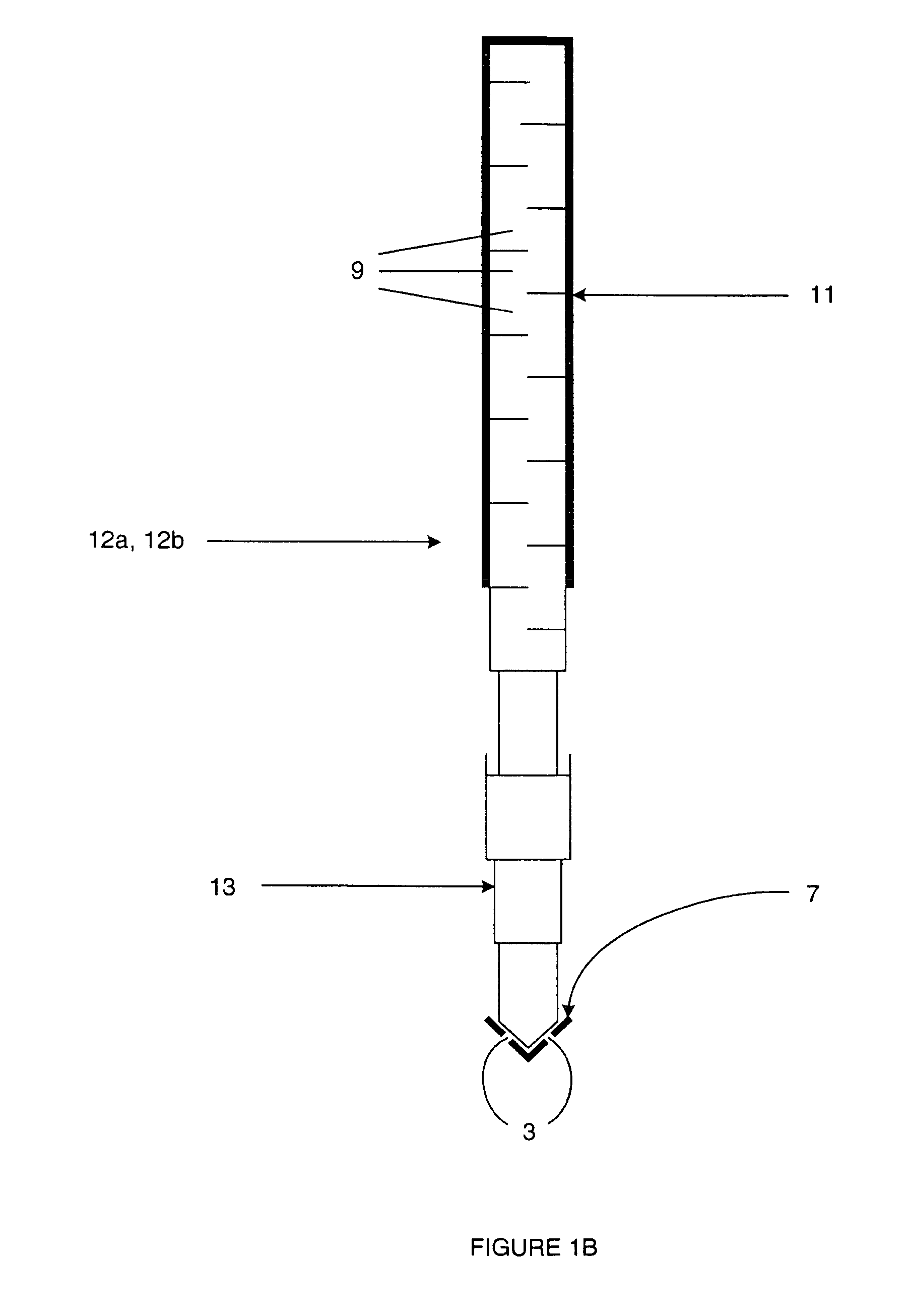
[0075]With reference to FIGS. 1A and 1B, an engine 8, such as an automotive vehicle engine, is generally shown having an injector arrangement comprising a first fuel injector 12a and a second fuel injector 12b. The fuel injectors 12a, 12b each have an injector valve needle 13 and a piezoelectric actuator 11 comprising a stack of piezoelectric elements 9. The piezoelectric actuator 11 is operable to control the position of an injector valve needle 13 relative to a valve needle seating 7. Depending on the voltage across the terminals of the piezoelectric actuator 11, the valve needle 13 is either caused to disengage the valve needle seating 7, in which case fuel is delivered into an associated combustion chamber / cylinder (not shown) of the engine 8 through a set of nozzle outlets 3; or is caused to engage the valve needle seating 7, in which case fuel delivery is prevented.
[0076]The fuel injectors 12a, 12b may, for example, be employed in a compression ignition internal combustion eng...
PUM
 Abstract
Description
Claims
Application Information
 - R&D
- Intellectual Property
- Life Sciences
- Materials
- Tech Scout
- Unparalleled Data Quality
- Higher Quality Content
- 60% Fewer Hallucinations
Browse by: Latest US Patents, China's latest patents, Technical Efficacy Thesaurus, Application Domain, Technology Topic, Popular Technical Reports.
© 2025 PatSnap. All rights reserved.Legal|Privacy policy|Modern Slavery Act Transparency Statement|Sitemap|About US| Contact US: help@patsnap.com


