Method and system for diagnosing mechanical, electromechanical or fluidic components

a technology of fluid components and diagnostic methods, applied in the direction of vibration measurement in solids, instruments, material analysis, etc., can solve the problems of increasing the electrical power consumption of the evaluation unit, affecting the accuracy of the diagnostic method, etc., to achieve the effect of low cos

Inactive Publication Date: 2009-04-09
SIEMENS AG
View PDF7 Cites 6 Cited by
  • Summary
  • Abstract
  • Description
  • Claims
  • Application Information

AI Technical Summary

Benefits of technology

[0005]An object of the invention is to provide a method and a system for diagnosing mechanical, electromechanical or fluidic components, said method and system being characterized by low expense.

Problems solved by technology

However, the known diagnostic system requires a spectral analysis of the measurement signal and hence involves a substantial overhead in terms of electronics and computing power.
It also entails an increase in the electrical power consumption of the evaluation unit.
Integration of the diagnostic method as an additional function into existing devices is therefore only rarely possible, since the additional power is often unavailable.

Method used


Image

  • Method and system for diagnosing mechanical, electromechanical or fluidic components
  • Method and system for diagnosing mechanical, electromechanical or fluidic components
  • Method and system for diagnosing mechanical, electromechanical or fluidic components

Examples


Embodiment Construction

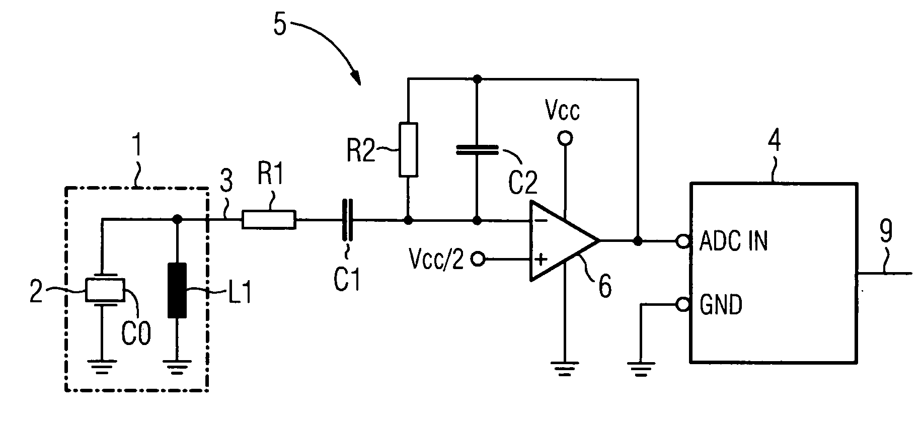
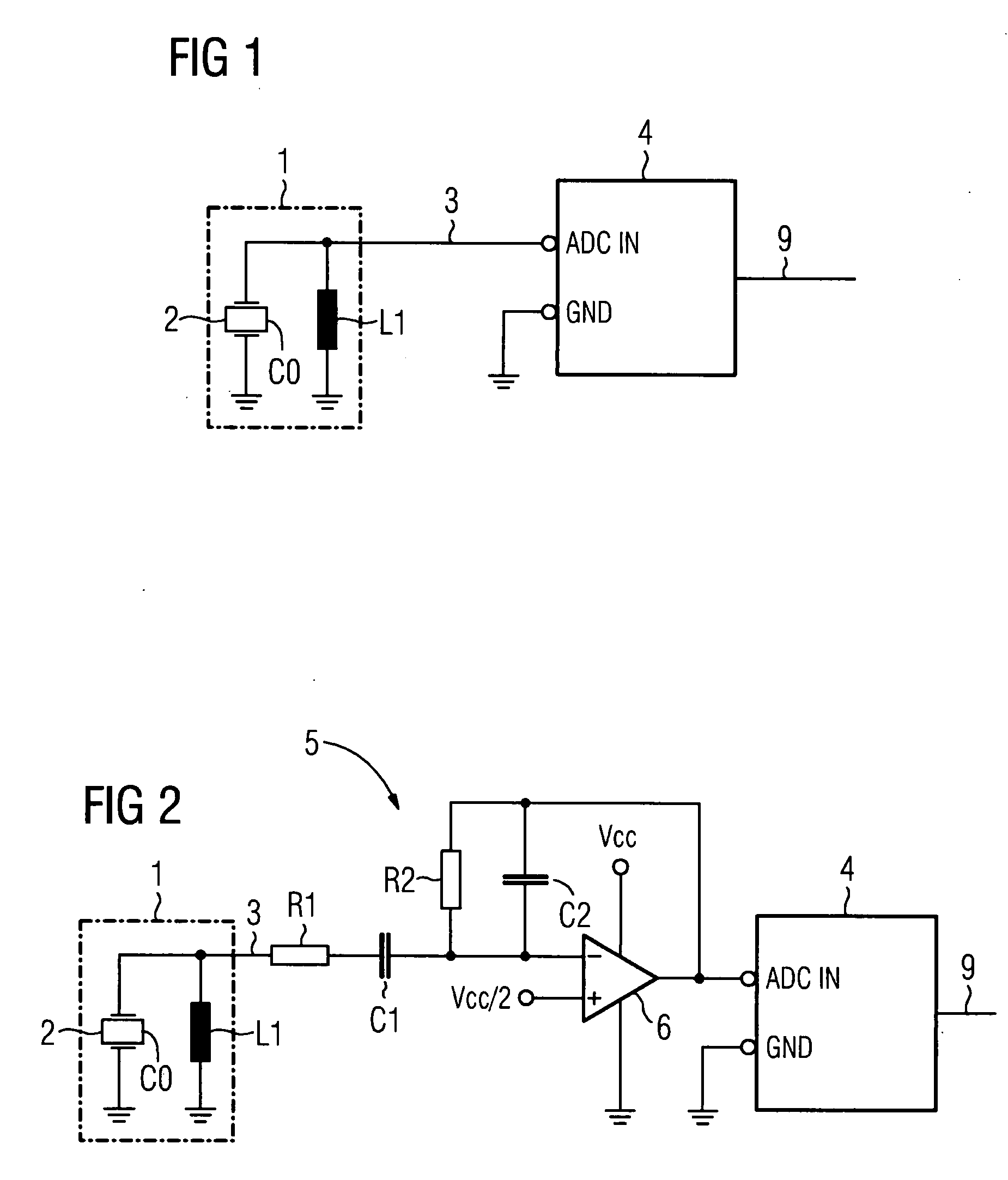
[0017]Referring to FIG. 1, a sensor 1 for structure-borne noise has a piezoceramic element 2 which is provided with electrodes. In the electrical equivalent circuit diagram, the piezoceramic element 2 has a capacitance C0 which can be modified by means of additional capacitors if necessary. An inductance L1 is connected in parallel with the piezoceramic element 2 and integrated in the sensor 1 as indicated by broken lines in FIG. 1. Alternatively, the inductance can be realized as a separate component. In order for the sensor 1 to emit a measurement signal 3 which essentially contains only signal components in a frequency range of interest, the mechanical resonance frequency of the piezoceramic element 2, the capacitance C0 and the inductance L1 are coordinated with one another in a suitable manner. The measurement signal 3 is applied to an analog input ADC IN of a microcontroller 4. The microcontroller 4 forms an analysis unit in which undersampling of the measurement signal 3 is p...


PUM


Abstract

There is described a diagnosis method and system comprising a sensor for structure-borne noise which emits a measuring signal in a bandwidth-filtered manner due to its mechanical resonant frequency, its capacity and an inductance. The system also comprises an evaluation device in which the measuring signal is subsampled measuring signal exceeds a defined threshold value. The system requires only a small number of electronic components and only little power supply capacity, thereby allowing diagnosis to be carried out without complication in existing devices, especially in field devices of process instrumentation for which only a limited amount of operating power is available. The method and system are especially advantageous for the recognition of valve leakage with an electropneumatic position controller.

Description

CROSS REFERENCE TO RELATED APPLICATIONS[0001]This application is the US National Stage of International Application No. PCT / EP2006 / 061984, filed May 2, 2006 and claims the benefit thereof. The International Application claims the benefits of German application No. 10 2005 020 900.9 DE filed May 4, 2005, both of the applications are incorporated by reference herein in their entirety.FIELD OF INVENTION[0002]The invention relates in one aspect to a method for diagnosing mechanical, electromechanical or fluidic components, in particular a valve which can be actuated by a positioner via a drive, and also to a system for diagnosing such components.BACKGROUND OF INVENTION[0003]By analyzing structure-borne noise it is possible to identify features which assist in the detection of faults or errors in mechanical, electromechanical or fluidic components. For example, EP 1 216 375 B1 discloses a diagnostic system for a valve which can be actuated by a positioner via a drive wherein the intensit...

Claims


Application Information

Patent Timeline
Patent Type & Authority Applications(United States)
IPC IPC(8): G01H17/00
CPCG01H1/00
Inventor PUTTMER, ALF
Owner SIEMENS AG
Why Eureka
Try Eureka