Viscosity measurement
- Summary
- Abstract
- Description
- Claims
- Application Information
AI Technical Summary
Benefits of technology
Problems solved by technology
Method used
Image
Examples
example
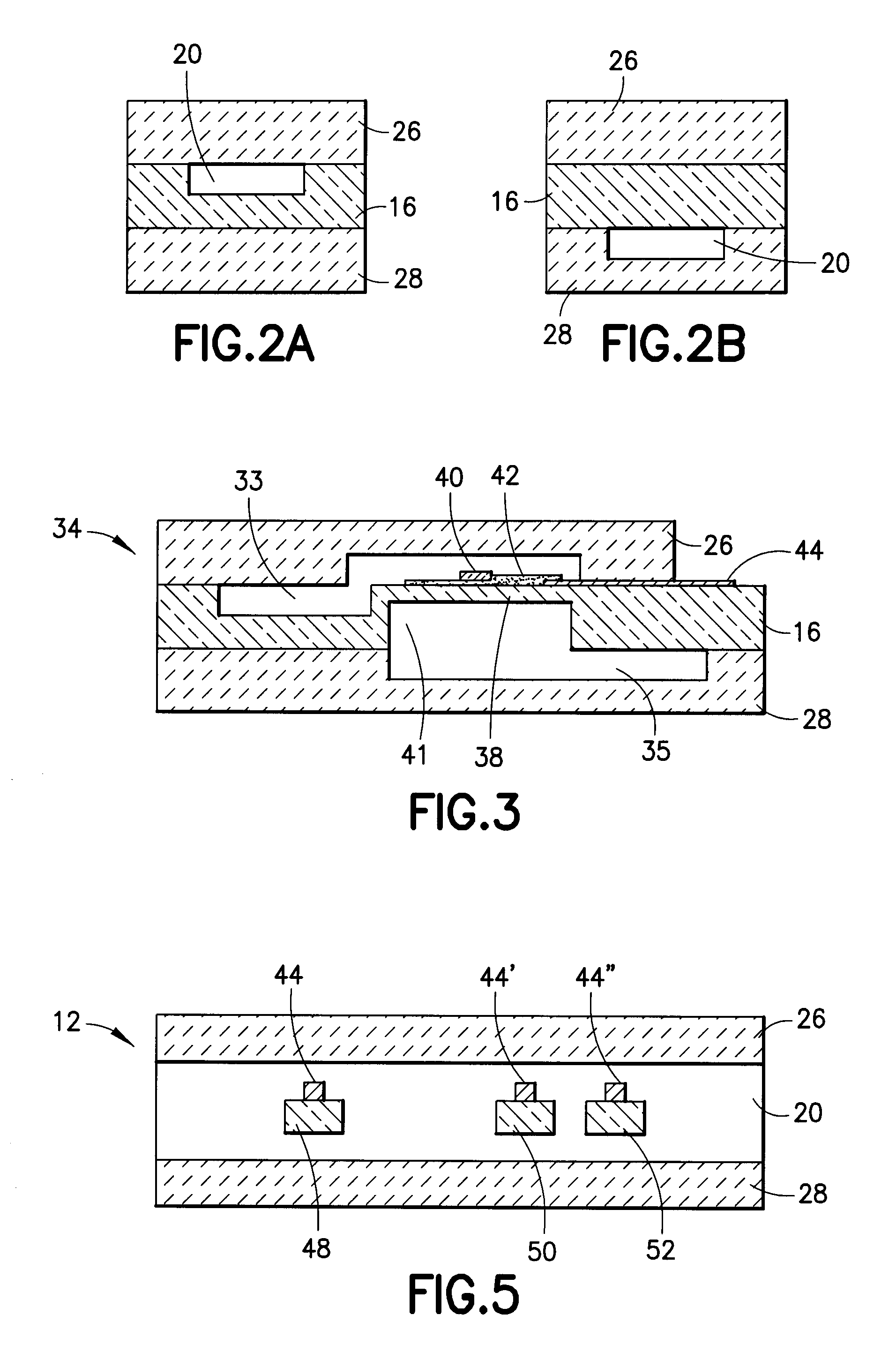
[0095]FIG. 11 graphically illustrates one embodiment of the flow rate sensor 12 of FIG. 5. A small volume of hexadecane was introduced into the flow rate sensor at a pump flow rate, in microliters per minute, determined by an external pump. Thermal pulses were generated by tracer emitter 48 and the time for the thermal pulse to reach first tracer detector 50 (represented by diamonds) and second tracer detector 52 (represented by triangles), measured as heat velocity in millimeters per second. The time for the thermal pulse to traverse the distance from the first tracer detector 50 to the second tracer detector 52 was also plotted in FIG. 9 (represented by circles) and is a straight line. This indicated that if the flow rate sensor 12 measured the heat velocity, the flow rate of a liquid may be calculated accurately. It was therefore not necessary to know a-priori the flow rate of a test fluid demonstrating that the micro-fluidic sensors described herein are effective for down hole a...
PUM
| Property | Measurement | Unit |
|---|---|---|
| rheological property | aaaaa | aaaaa |
| pressure drop | aaaaa | aaaaa |
| flow rate | aaaaa | aaaaa |
Abstract
Description
Claims
Application Information
 - R&D
- Intellectual Property
- Life Sciences
- Materials
- Tech Scout
- Unparalleled Data Quality
- Higher Quality Content
- 60% Fewer Hallucinations
Browse by: Latest US Patents, China's latest patents, Technical Efficacy Thesaurus, Application Domain, Technology Topic, Popular Technical Reports.
© 2025 PatSnap. All rights reserved.Legal|Privacy policy|Modern Slavery Act Transparency Statement|Sitemap|About US| Contact US: help@patsnap.com


