
Vestibular Stimulation System

a technology of vestibular stimulation and spondylosis, which is applied in the field of vestibular stimulation system, can solve the problems of significant challenge and the provision of an apparatus that allows

Active Publication Date: 2009-03-26
PHILIPS RS NORTH AMERICA LLC
View PDF41 Cites 212 Cited by
  • Summary
  • Abstract
  • Description
  • Claims
  • Application Information

AI Technical Summary

Benefits of technology

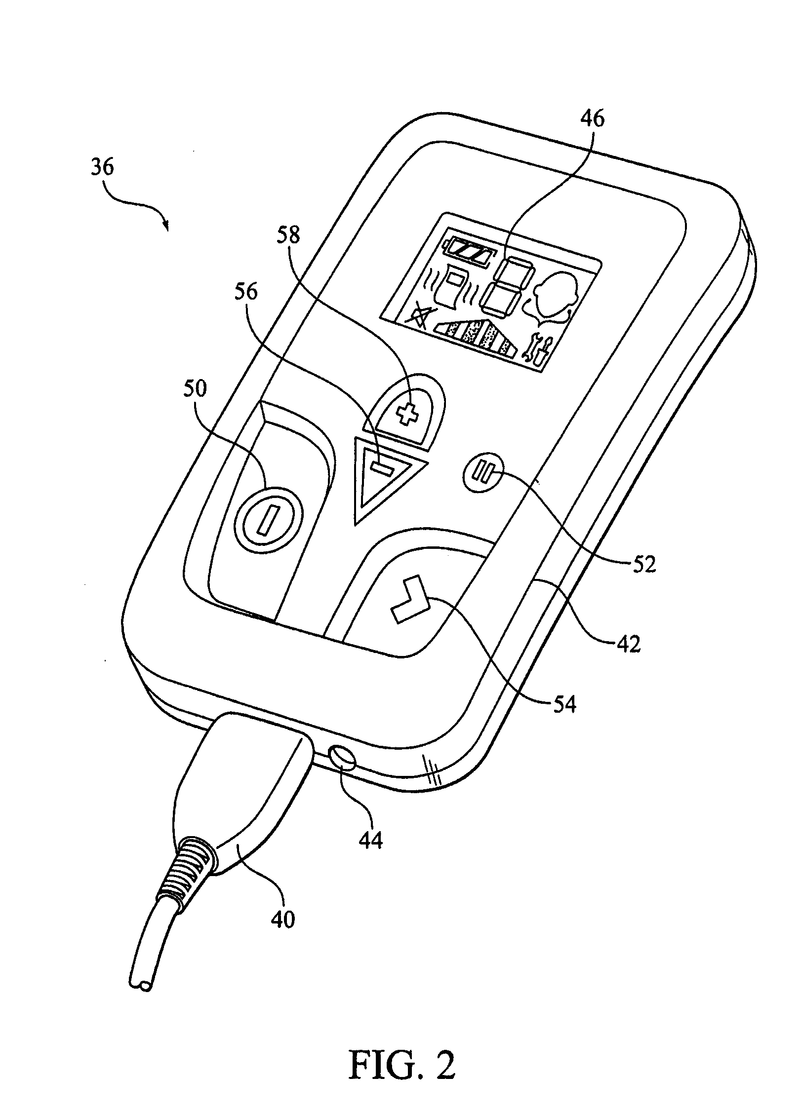
[0009]In accordance with the present invention, there is provided an apparatus for the stimulation of the vestibular system. The apparatus includes a housing, a power supply disposed in the housing, an electrode assembly adapted to be coupled to the housing, and a controller disposed in the housing and operatively coupled to the power supply. The controller controls delivery of energy from the power supply to the electrode assembly. An input element is disposed on an exterior surface of the housing. The input element is manually manipulated to control the operation of the vestibular stimulation system. A display is also disposed on an exterior surface of the housing to provide visual information regarding the operation of the vestibular stimulation system. A mounting assembly mounts the housing on such a user.
[0010]In a further embodiment, a method of providing vestibular stimulation to a user is provided. This method includes providing a vestibular stimulation system that includes (1) a housing, (2) a power supply disposed in the housing, (3) a controller disposed in the housing and operatively coupled to the power supply to control delivery of energy from the power supply to the electrode assembly, (4) an input element disposed on an exterior surface of the housing, and (6) a display disposed on an exterior surface of the housing. This method further includes coupling an electrode assembly to the housing, mounting the housing on such a user using a mounting assembly coupled to the housing, and delivering stimulation energy to a user by providing energy from the power supply to the electrode assembly. The method further includes controlling the operation of the vestibular stimulation system by manually manipulating the input element, and providing visual information regarding the operation of the vestibular stimulation system using the display.
[0011]These and other objects, features, and characteristics of the present invention, as well as the methods of operation and functions of the related elements of structure and the combination of parts and economies of manufacture, will become more apparent upon consideration of the following description and the appended claims with reference to the accompanying drawings, all of which form a part of this specification, wherein like reference numerals designate corresponding parts in the various figures. It is to be expressly understood, however, that the drawings are for the purpose of illustration and description only and are not intended as a definition of the limits of the invention. As used in the specification and in the claims, the singular form of “a”, “an”, and “the” include plural referents unless the context clearly dictates otherwise.

Problems solved by technology

Disorders of the vestibular system may result in such physiological disorders as dizziness, vertigo, and nausea with symptoms ranging in severity from mild to completely debilitating.
While this concept is simple to conceptualize, providing an apparatus that allows the patient to fall asleep and sleep comfortably without becoming tangled in electrical wires or having their sleep disrupted by a bulky stimulation unit is a significant challenge.
There are also numerous challenges in delivering stimulation energy in a safe and effective fashion.

Method used


Image

  • Vestibular Stimulation System
  • Vestibular Stimulation System
  • Vestibular Stimulation System

Examples


Embodiment Construction

I. System Architecture / Hardware

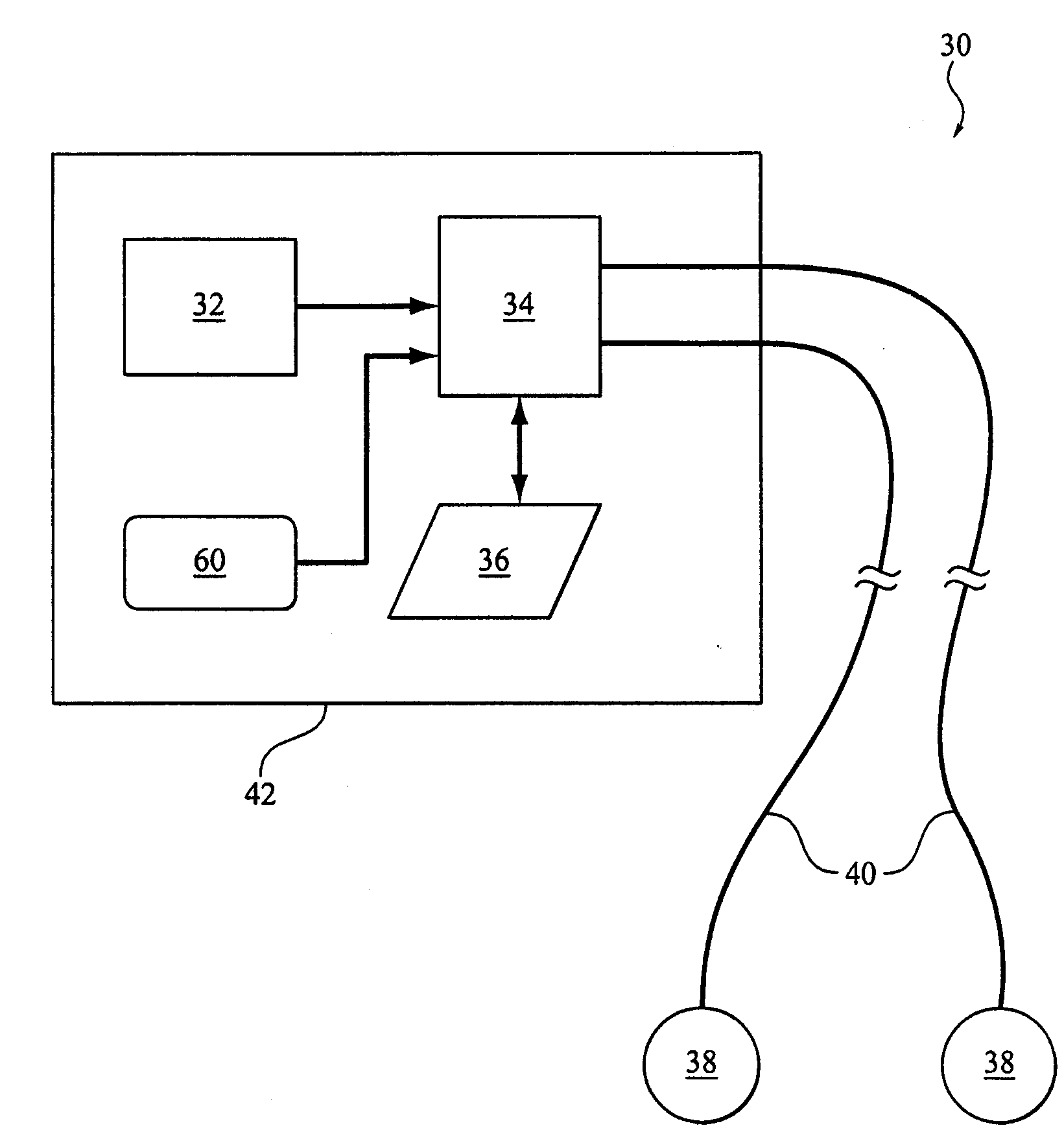
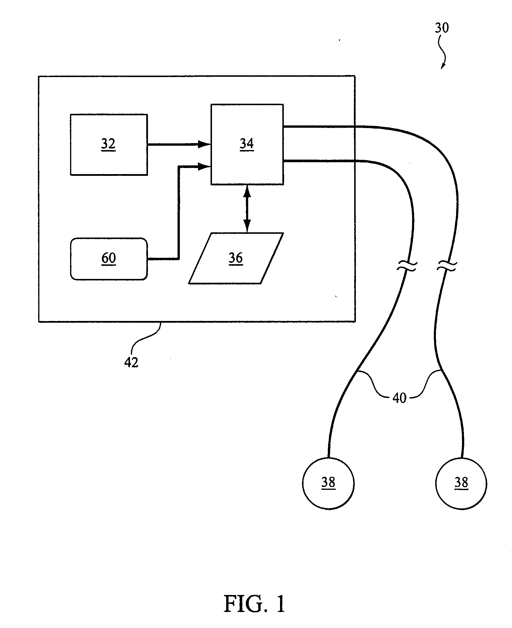
[0041]Referring now to FIGS. 1 and 2, the basic components of a vestibular stimulation system 30 according to the principles of the present invention will now be described. Vestibular stimulation system 30 includes a power supply 32, a controller 34, an input / output interface 36, and a pair of electrodes 38. Wires or electrical leads 40 couple the controller and / or power supply to the electrodes. The electrical leads and the electrodes that are coupled to the electrical leads in either a fixed or removable fashion, are referred to as the electrode assembly.

[0042]As discussed in greater detail below, vestibular stimulation system 30 also includes one or more optional sensors 60, such as temperature, light, sound, motion, acceleration, position, EMG, EOG, ECC, pulse oximetry, heart rate, sleep state, rapid eye movement (REM), galvanic skin sensor, nerve activity, sweat detectors, vessel constriction or dilatation sensors, or other sensors that provide in...


PUM


Abstract

A vestibular stimulation system and method that includes a housing, a power supply disposed in the housing, an electrode assembly adapted to be coupled to the housing, and a controller disposed in the housing and operatively coupled to the power supply. The controller controls the delivery of energy from the power supply to the electrode assembly. An input element is also disposed on an exterior surface of the housing. The input element is manually manipulated to control the operation of the vestibular stimulation system. A display disposed on an exterior surface of the housing provides visual information regarding the operation of the vestibular stimulation system. A mounting assembly is coupled to the housing to mount the housing on such a user.

Description

CROSS-REFERENCE TO RELATED APPLICATIONS[0001]This application claims priority under 35 U.S.C. § 119(e) from provisional U.S. patent application No. 60 / 974,136, filed Sep. 21, 2007, the contents of which are incorporated herein by reference.BACKGROUND OF THE INVENTION[0002]1. Field of the Invention[0003]The present invention pertains to a vestibular system and method of operating such as system to maximize the effectiveness of the therapy and the comfort to the user, while making the treatment as easy as possible.[0004]2. Description of the Related Art[0005]The vestibular system is responsible for the detection of the position and motion of the head in space. The semicircular canals and otolythic organs, which are located in the inner ear, are the sensory organs of the vestibular system and collect head position and motion information and transmit it to the central nervous system via the eighth cranial nerve.[0006]Stimulation of either the semicircular canals and / or otolythic organs,...

Claims


Application Information

Patent Timeline
Patent Type & Authority Applications(United States)
IPC IPC(8): A61N1/08
CPCA61N1/0456A61N1/0472A61N1/0484A61N1/0492A61N1/36031A61N1/36034A61N1/36036A61N1/36535A61N1/36542
Inventor PAUL, ZACHARY D.LATTNER, STEFANIEGIOVANNELLI, BENJAMIN A.COLBAUGH, MICHAEL E.KIRBY, TODDWELLS, KEVINBROADLEY, WILLIAM H.VANGURA, ALCESSNA, MICHAEL
Owner PHILIPS RS NORTH AMERICA LLC
Learn More