Eureka AIR delivers breakthrough ideas for toughest innovation challenges, trusted by R&D personnel around the world.

Method and apparatus for wireplasty bone resection

a wireplasty and bone resection technology, applied in the field of wireplasty bone resection, can solve the problems of inability to consistently and/or properly locate and orient the distal femoral resection in a quick and efficient manner, the approach to using such planar saw blade instrumentation systems all possess certain limitations and liabilities, and the kind of error is further compounded. , to achieve the effect of reducing the incision size, reducing the risk of soft tissue damage, and reducing the size of the bone resection and bone resection and bone resection and bone resection and bone resection and wireplasty bone resection and wireplasty bone resection and wireplasty bone resection and wireplasty is a wireplasty and bone resection and wire resection and wire resection and which is applied in the field of wire resection and other problems, achieves the effect of resection and other a wireplasty bone re bone resection method and bone resection method, a wireplasty bone resection technique, applied in the field of wireplas

Inactive Publication Date: 2009-03-26
BIOMET MFG CORP
View PDF100 Cites 61 Cited by
  • Summary
  • Abstract
  • Description
  • Claims
  • Application Information

AI Technical Summary

Benefits of technology

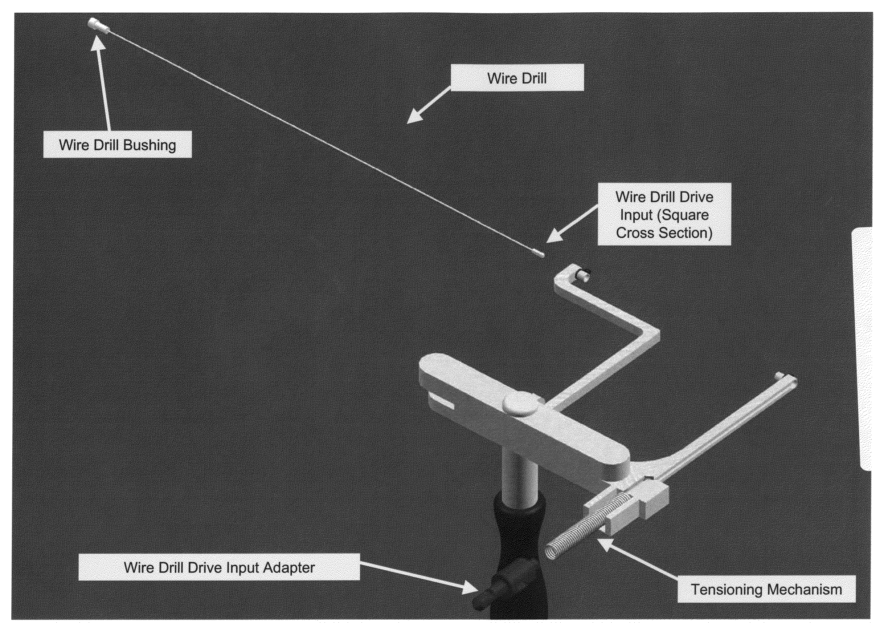
[0012]The present invention provides for a cutting tool to be utilized in the resection or removal of bone tissue from patients. The cutting tool includes a handle that tensions a wire or cable-like cutting member with a small diameter between at least two stationary points on the handle to present a thin cutting profile. The design of the cutting tool includes features that protect against soft tissue damage and minimize the incision size necessary to utilize the tool. Some embodiments feature details of the cutting tool that interface with a surgical cutting guide system. Other embodiments describe a cutting tool with a selectively changeable length of the cutting profile of the wire cutting member. In one embodiment, the wire cutting member of the cutting tool is energized by mechanical energy in the form of a unidirectional rotation of the cutting member, a mechanical vibration of the cutting member, or an oscillating movement of the wire cutting member. In another embodiment, a very small diameter wire is used to permit manual manipulation of the cutting tool, but still provide sufficient force to effect cutting of the bone.
[0013]It is an often repeated rule of thumb for orthopedic surgeons that a “Well placed, but poorly designed implant will perform well clinically, while a poorly placed, well designed implant will perform poorly clinically.” The present invention provides a method and apparatus for reducing implant placement errors in order to create more reproducible, consistently excellent clinical results in a manner that is less dependent upon the manual skill of the surgeon creating a resected surface. Importantly, some of the embodiments of the present invention demonstrate the ability to be inserted into small incisions and yet extend the cutting surfaces of the tool significantly across the bone to be cut beneath the soft tissues of the joint, thus cutting bone surfaces that are not readily visible to the surgeon during the procedure.

Problems solved by technology

Past efforts have not been successful in consistently and / or properly locating and orienting distal femoral resections in a quick and efficient manner.
Unfortunately, present approaches to using such planar saw blade instrumentation systems all possess certain limitations and liabilities.
This kind of error is further compounded by the “tolerance stacking,” inherent in the use of multiple alignment guides and cutting guides.
Another error inherent in these systems further adding to mal-alignment is deflection of the oscillating saw blade during the cutting process.
The use of an oscillating saw blade is very skill intensive as the blade will also follow the path of least resistance through the bone and deflect in a manner creating variations in the cut surfaces which further contribute to prosthesis mal-alignment as well as poor fit between the prosthesis and the resection surfaces.
Despite the fact that the oscillating saw has been used in TKA and other bone resection procedures for more than 30 years, there are still reports of incidences where poor cuts result in significant gaps in the fit between the implant and the bone.
The safety of these saws is also questionable as minor incidences of misuse can result in serious harm and disability.
Generally, the problems of precision, accuracy and safety of these other cutting instruments are even greater than with an oscillating saw.
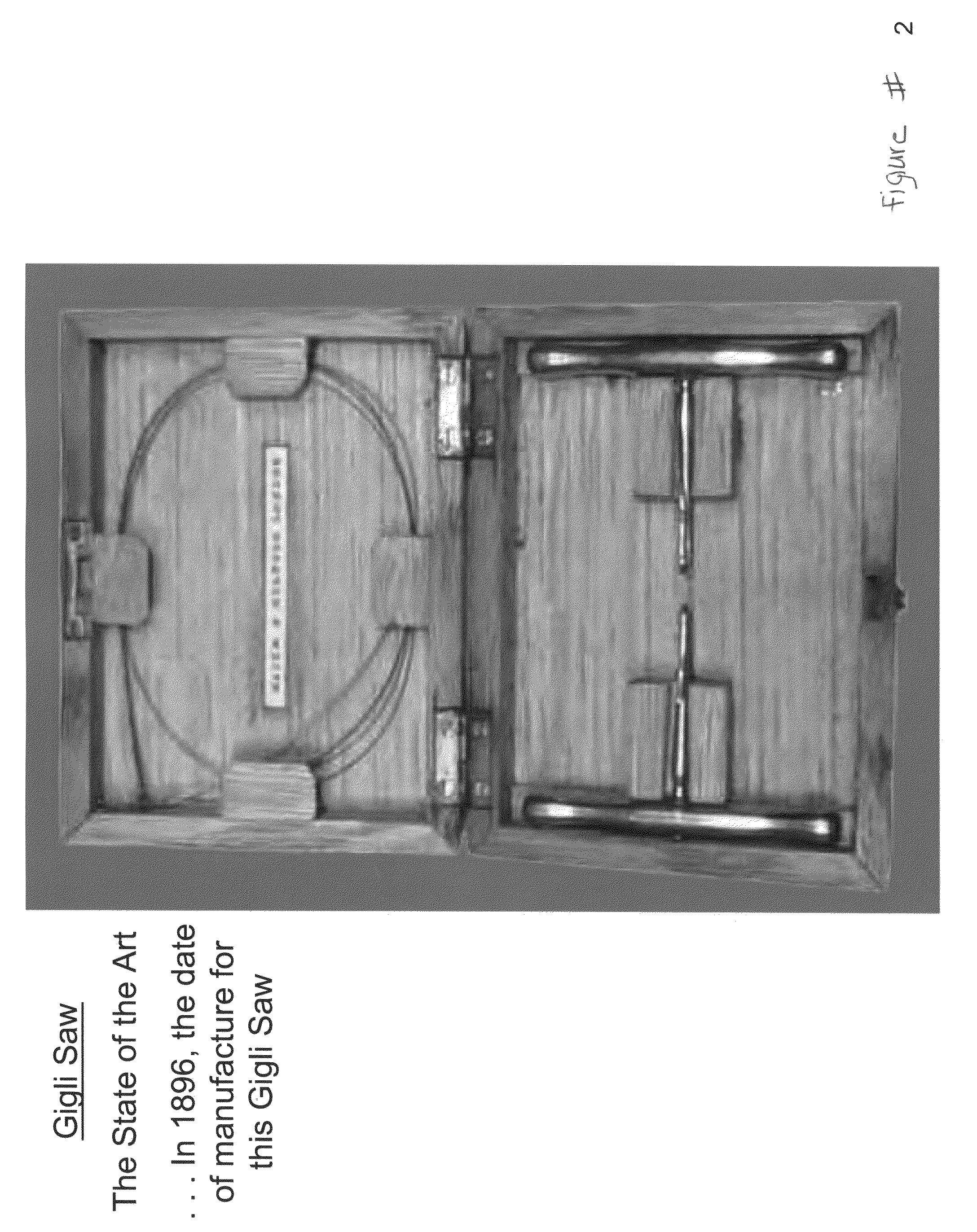
Although conventional chain saws and gigli saws can be very efficient general purpose cutting tools, these saws have little ability to be guided and aligned so as to make the precise and accurate resection cuts required for effective implants.

Method used


Image

  • Method and apparatus for wireplasty bone resection
  • Method and apparatus for wireplasty bone resection
  • Method and apparatus for wireplasty bone resection

Examples


Embodiment Construction

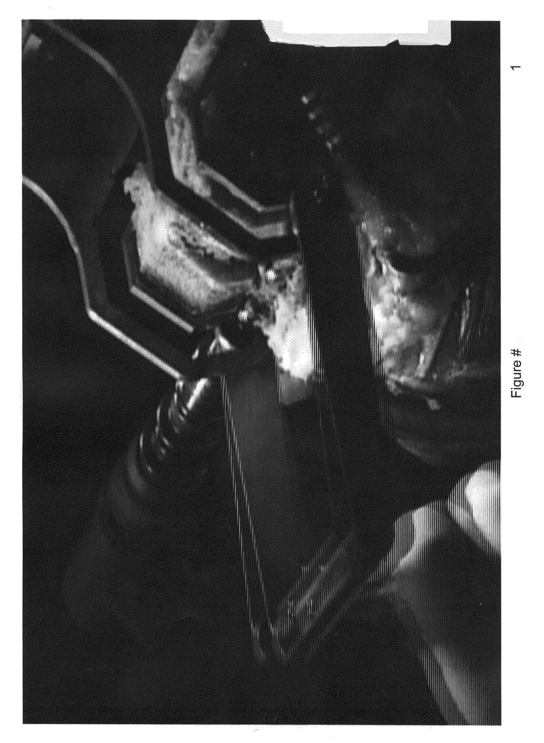
[0018]FIGS. 1 and 41 shows a Profile Based Resection (PBR) type cutting guide in conjunction with a side cutting drill in action. This will be recognized as an embodiment of the inventions of U.S. Pat. No. 5,810,827. The basic components are the side cutting drill, the PBR guide, the guide handle, and fixation features of the cutting guide, which in this case are cannulated screws or drill guides and 0.125 inch drill pins. The PBR guide possesses at least one plate to which the guide handle is engaged during cutting. A drawback about this particular design or embodiment of the PBR technology is that, in the hands of an average surgeon, it required an incision length of at least 6 inches in order to be attached to the femur and utilized to resect or cut bone. It is an object of some of the embodiments of the present invention to provide for improvements upon this design enabling it to be used in a manner that is less invasive or minimally invasive while maintaining the outstanding re...


PUM


Abstract

A cutting tool to be utilized in the resection or removal of bone tissue from patients includes a handle that tensions a wire or cable-like cutting member with a small diameter between at least two features on the handle to present a thin cutting profile. The design of the cutting tool includes features that protect against soft tissue damage and minimize the incision size necessary to utilize the tool. Some embodiments feature details of the cutting tool that interface with a surgical cutting guide system. Other embodiments describe a cutting tool with a selectively changeable length of the cutting profile of the wire cutting member. In one embodiment, the wire cutting member of the cutting tool is energized by mechanical energy in the form of a unidirectional rotation of the cutting member, a mechanical vibration of the cutting member, or an oscillating movement of the wire cutting member.

Description

RELATED APPLICATION [0001]This application is a continuation of application Ser. No. 11 / 049,634 filed Feb. 2, 2005, which claims the benefit of U.S. Provisional Application No. 60 / 540,992 filed Feb. 2, 2004, and claims priority to continuation application Ser. No. 11 / 036,584 filed Jan. 14, 2005, which claims the benefit of U.S. Provisional Application No. 60 / 536,320 filed Jan. 14, 2004, each of which is hereby fully incorporated herein by reference.BACKGROUND OF THE INVENTION[0002]1. Field of the Invention[0003]This invention generally relates to methods and apparatus for bone resection to allow for the interconnection or attachment of various prosthetic devices with respect to the patient. More particularly, the present invention relates to the use of a wireplasty bone resection technique in which wires or cables act as bone cutting tools.[0004]2. Background Art[0005]Different methods and apparatus have been developed in the past to enable a surgeon to remove bony material to creat...

Claims


Application Information

Patent Timeline
Patent Type & Authority Applications(United States)
IPC IPC(8): A61B17/00A61F5/00
CPCA61B17/14A61B17/141A61B17/1668A61B2017/143A61B2017/145A61B2017/1602A61B17/1675A61B17/149
Inventor HAINES, TIMOTHY G.
Owner BIOMET MFG CORP
Why Eureka
Eureka Blog
Learn More