
Apparatus, system, and method to manage the generation and use of hybrid electric power

a hybrid electric power and hybrid technology, applied in mechanical power/torque control, wind energy generation, dc source parallel operation, etc., can solve the problems of inability to meet instantaneously the request for increased power/energy, user control of the source of most non-fuel-based energy, and inability to easily store excess sunlight or wind for later use. to achieve the effect of efficient management of energy conversion delay

Inactive Publication Date: 2009-03-19
TRULITE INC
View PDF101 Cites 163 Cited by
  • Summary
  • Abstract
  • Description
  • Claims
  • Application Information

AI Technical Summary

Benefits of technology

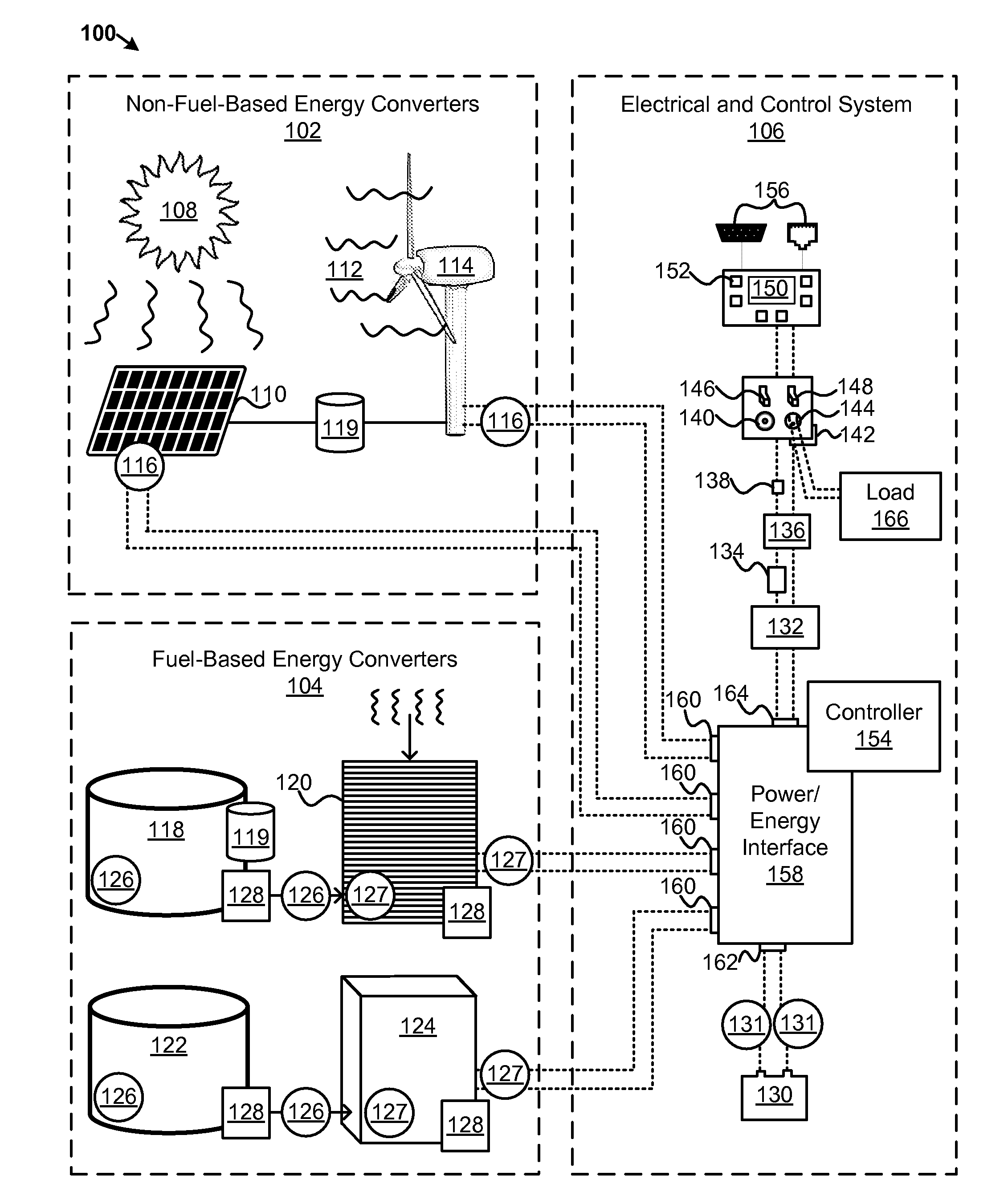
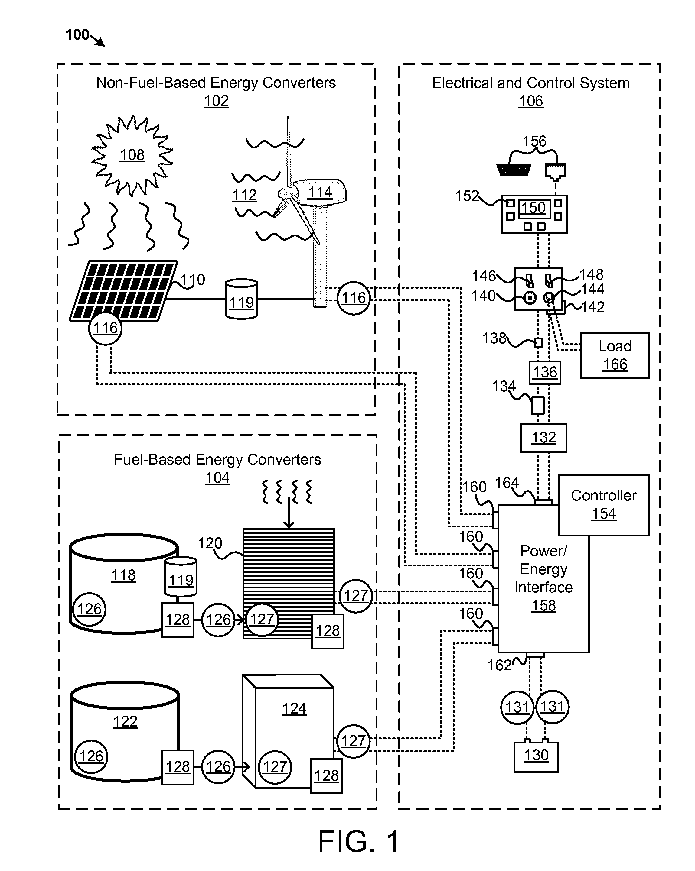
[0008]From the foregoing discussion, it should be apparent that a need exists for an apparatus, system, and method that manages the generation and use of hybrid electric power. Beneficially, such an apparatus, system, and method would efficiently manage energy conversion delays and balance electric power that is delivered to an electric load.

Problems solved by technology

However, users have little control over the sources of most non-fuel-based energy, such as the sun and the wind.
Alternatively, if one is using less power / energy than is being generated, one cannot easily store excess sunlight or wind for later use.
A request for increased power / energy cannot always be met instantaneously, however, because of energy conversion delays inherent in fuel-based energy generation.
For example, increasing a flow of hydrogen to a hydrogen fuel cell may not cause an immediate increase in the output of electrical power from the hydrogen fuel cell.
The increased hydrogen may also need to be converted to hydrogen from a hydrogen fuel source, which may introduce additional delays.
Other fuel-based energy often has similar delays.

Method used


Image

  • Apparatus, system, and method to manage the generation and use of hybrid electric power
  • Apparatus, system, and method to manage the generation and use of hybrid electric power
  • Apparatus, system, and method to manage the generation and use of hybrid electric power

Examples


Embodiment Construction

[0034]Many of the functional units described in this specification have been labeled as modules, in order to more particularly emphasize their implementation independence. For example, a module may be implemented as a hardware circuit comprising custom VLSI circuits or gate arrays, off-the-shelf semiconductors such as logic chips, transistors, or other discrete components. A module may also be implemented in programmable hardware devices such as field programmable gate arrays, programmable array logic, programmable logic devices or the like.

[0035]Modules may also be implemented in software for execution by various types of processors. An identified module of executable code may, for instance, comprise one or more physical or logical blocks of computer instructions which may, for instance, be organized as an object, procedure, or function. Nevertheless, the executables of an identified module need not be physically located together, but may comprise disparate instructions stored in d...


PUM


Abstract

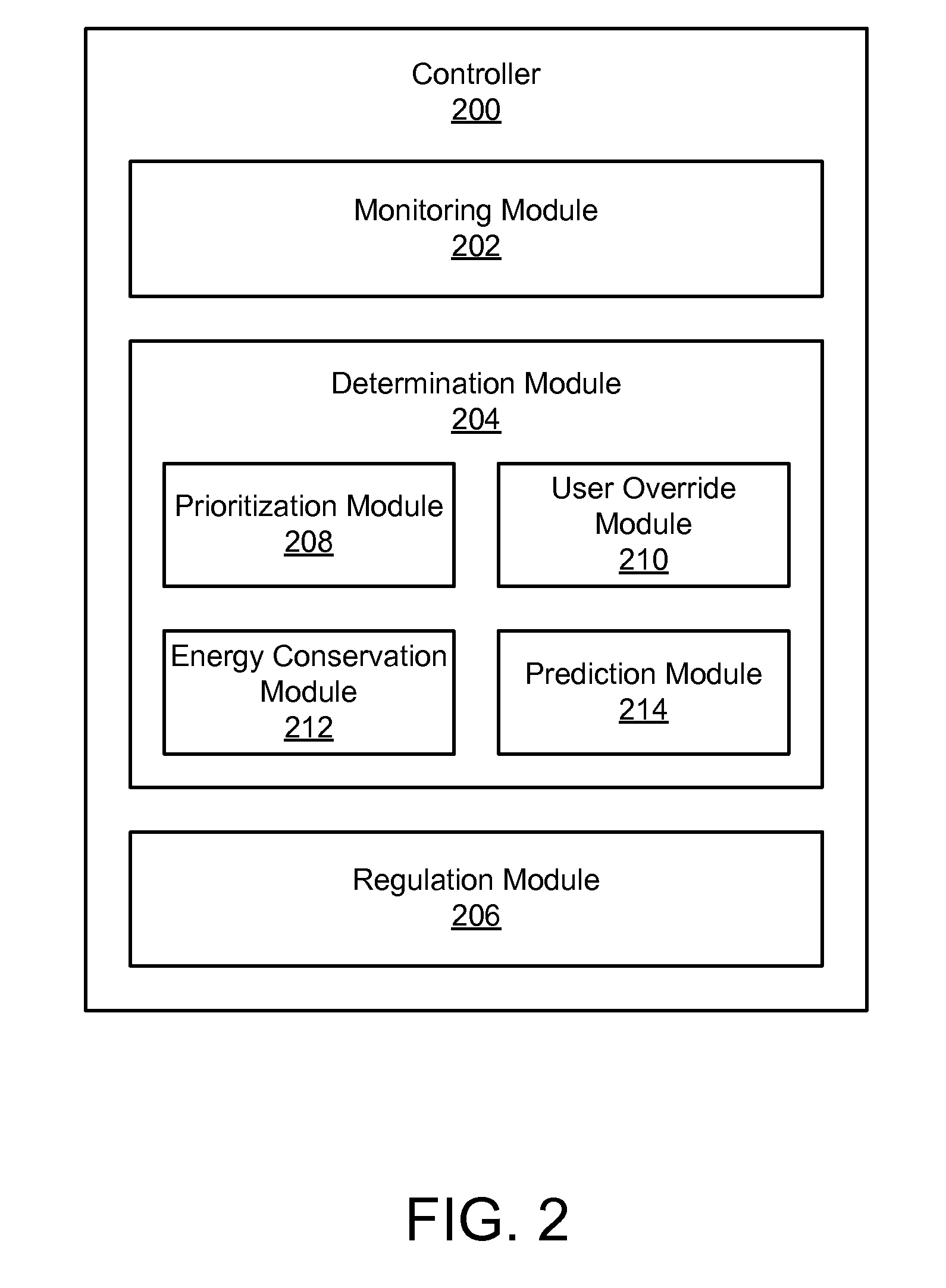
An apparatus, system, and method are disclosed to manage the generation and use of hybrid electric power. A monitoring module receives signals from one or more sensors. The signals comprise power level information of an electric energy storage device, power level information of one or more energy converters, and power level information of an electric load. A determination module compares the signals to determine whether electric power from the energy converters satisfies the electric load. A regulation module adjusts the electric power from the energy converters in response to a determination by the determination module that the electric power from the energy converters does not satisfy an electric load threshold.

Description

CROSS-REFERENCES TO RELATED APPLICATIONS[0001]This application claims the benefit of U.S. Provisional Patent Application No. 60 / 951,925 entitled “APPARATUS, SYSTEM, AND METHOD TO MANAGE THE GENERATION AND USE OF HYBRID ELECTRIC POWER” and filed on Jul. 25, 2007 for Ken Pearson, et. al which is incorporated herein by reference. This application incorporates by reference U.S. patent application Ser. No. 10 / 459,991 filed Jun. 11, 2003, Ser. No. 11 / 270,947 filed Nov. 12, 2005, Ser. No. 11 / 740,349 filed Apr. 26, 2007, Ser. No. 11 / 828,265 filed Jul. 25, 2007, Ser. No. 11 / 829,019 filed Jul. 26, 2007, Ser. No. 11 / 829,035 filed Jul. 26, 2007, Ser. No. 12 / 179,554 filed Jul. 24, 2008, and Ser. No. 12 / 179,578 filed Jul. 24, 2008; and U.S. Provisional Patent Application Ser. No. 60 / 951,903 filed Jul. 25, 2007, 60 / 951,907 filed Jul. 25, 2007, and 61 / 059,743 filed Jun. 6, 2008, each of which is incorporated by reference herein in its entirety.BACKGROUND OF THE INVENTION[0002]1. Field of the Invent...

Claims


Application Information

Patent Timeline
IPC IPC(8): H02J3/46H02J3/32
CPCH01M8/04619Y02E10/763H01M8/0494H01M8/04947H01M8/0618H01M8/065H01M8/0656H01M16/006H01M2008/1095H01M2008/1293H01M2250/402H02J1/102H02J7/34Y02B90/12Y02E60/50Y02E60/525H02J3/381H02J3/387H02J3/383H02J3/386H02J3/382Y02E10/563H01M8/04626H02J2300/40H02J2300/10H02J2300/30H02J2300/28H02J2300/20H02J2300/24Y02B90/10Y02E10/56Y02E10/76Y02E60/10H02J3/466
Inventor PEARSON, KENBRYDON, CHRISYOU, EUGENEWANG, GUANGDE
Owner TRULITE INC
Learn More