
Systems and methods for collecting solar energy for conversion to electrical energy

a technology of solar energy and electrical energy, applied in the field of solar energy, can solve the problems of affecting the cost and conversion efficiency of electrical energy, the price per watt has leveled, and the cost of manufacturing is high

Inactive Publication Date: 2009-03-19
PULSAR ENERGY
View PDF25 Cites 15 Cited by
  • Summary
  • Abstract
  • Description
  • Claims
  • Application Information

AI Technical Summary

Benefits of technology

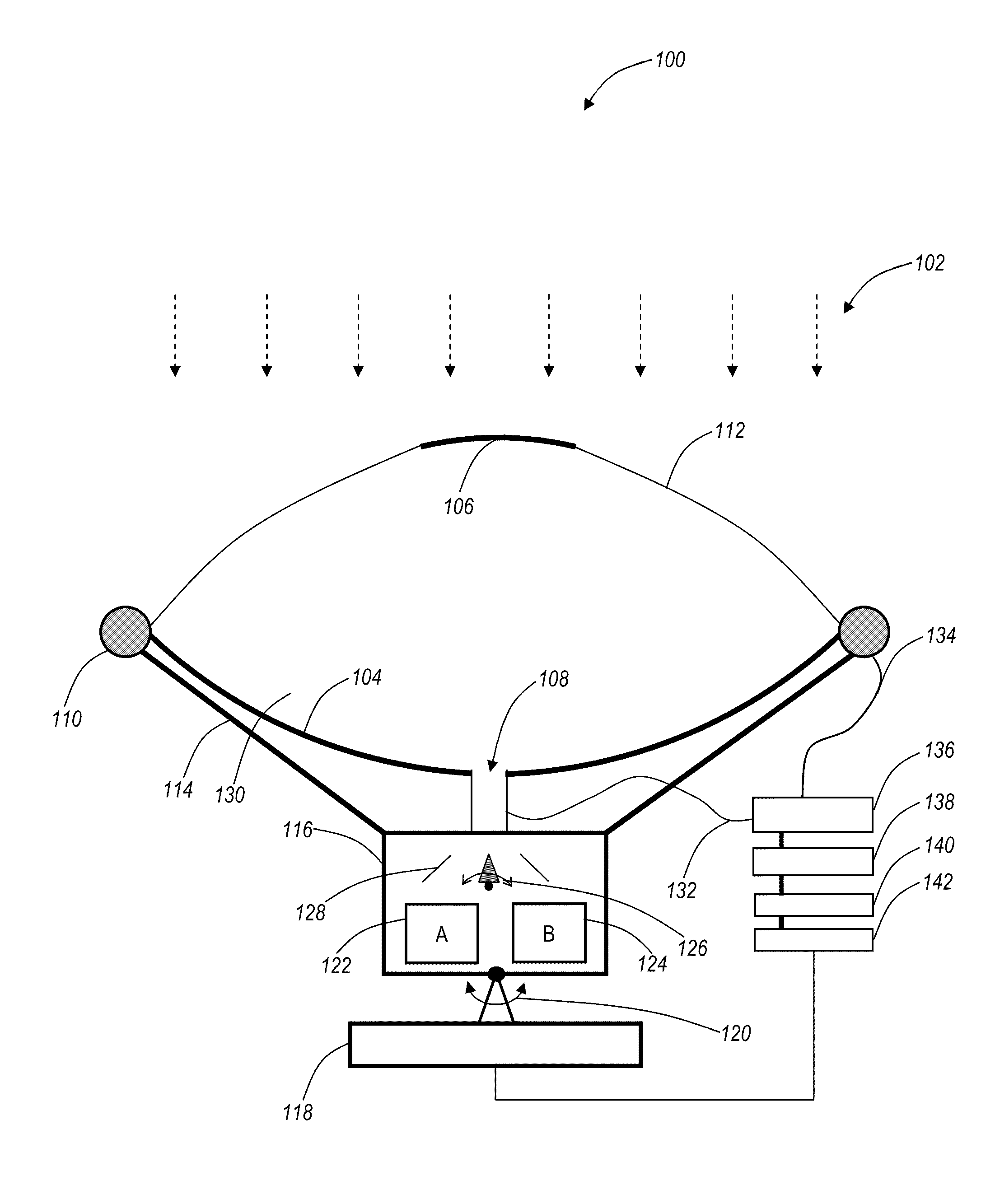
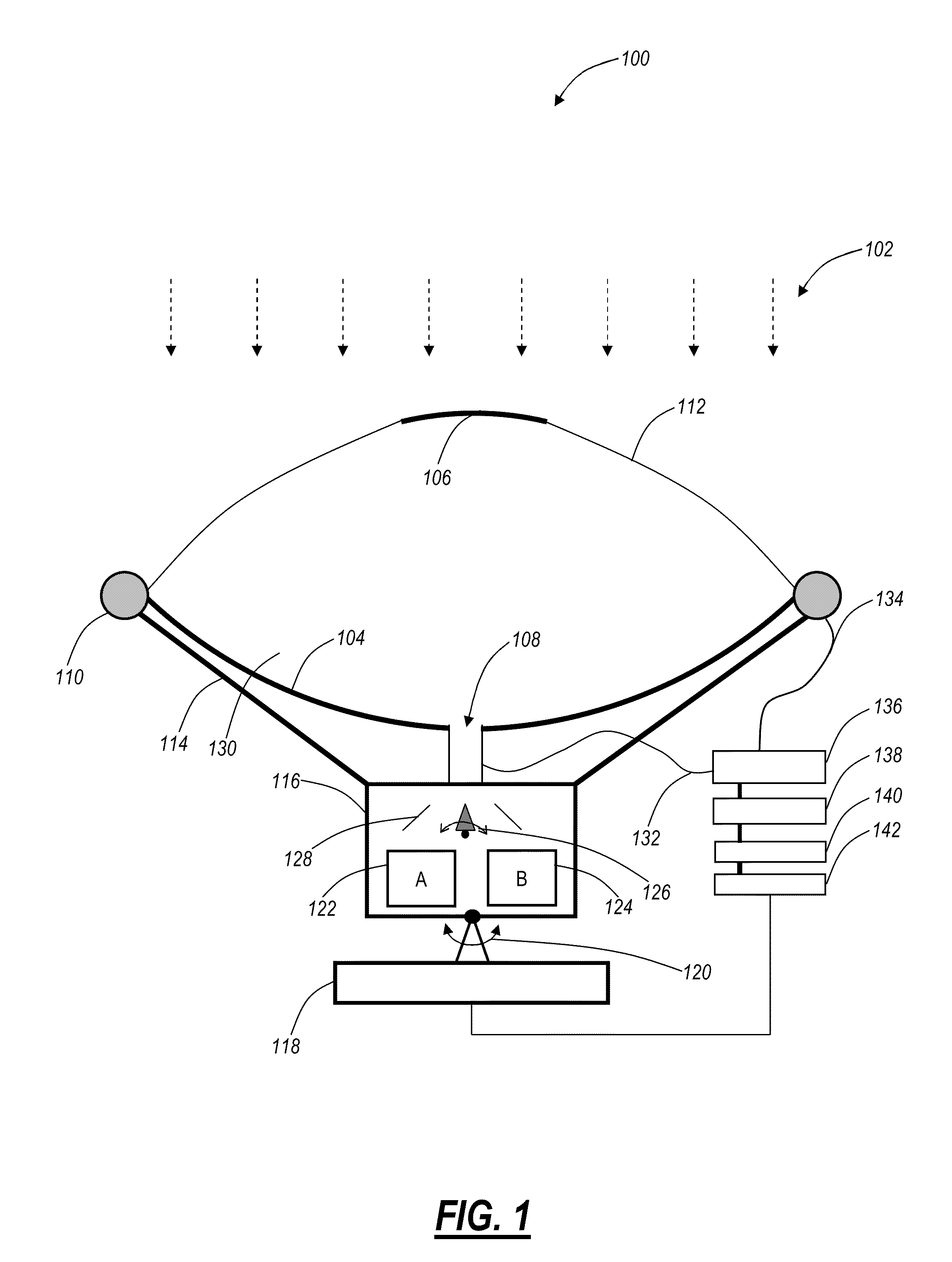
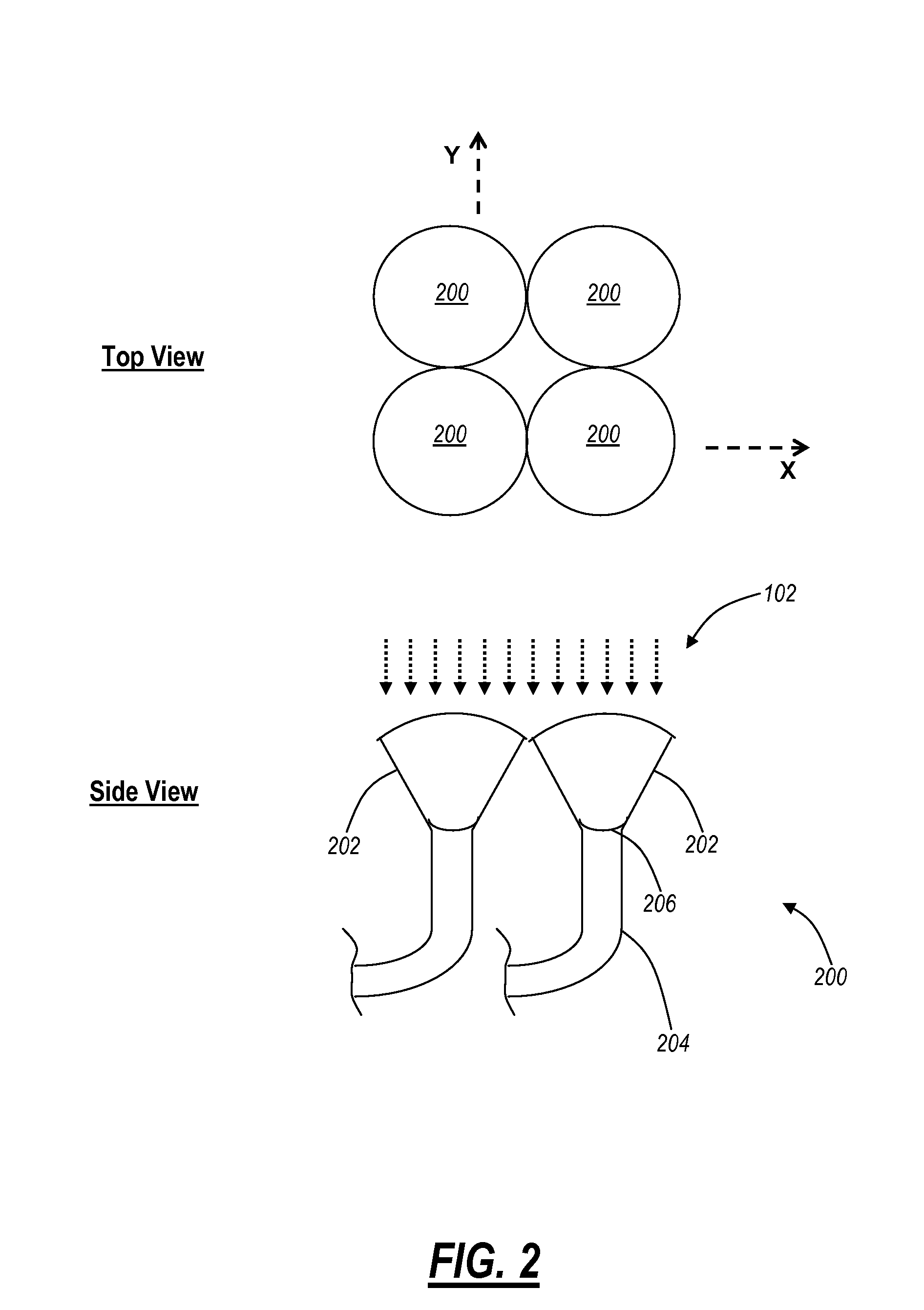
[0007]In various exemplary embodiments, the present invention provides systems and methods for collecting and converting solar energy into electrical energy by using a solar collector and one or more thermodynamic closed-cycle heat engines. The present invention includes new designs for solar collectors that concentrate solar energy, and mechanisms for transporting and transferring the concentrated solar energy directly into the working fluid (e.g., a liquid, a gas, or a phase change substance) of the closed cycle thermodynamic engines without heating the outside surface of the engines. The system includes one or more solar collectors and a delivery system to deliver concentrated energy from the collectors directly into working fluid of thermodynamic closed-cycle engines (such as Stirling or Rankine type of engines or variations of these). Advantageously, the delivery system avoids heating an outside surface of the engines as is done in conventional designs. Additionally, the delivery system can be configured to distribute collected energy to multiple engines with offset heating cycles.
[0008]In an exemplary embodiment of the present invention, a system for collecting solar energy for one or more of thermodynamic engines includes one or more thermodynamic engines each with one or more chambers; a solar collector configured to concentrate solar energy; and a distribution mechanism configured to distribute the concentrated solar energy to the one or more chambers in each of the one or more thermodynamic engines for a predetermined period of time. The distribution mechanism is configured to distribute the concentrated solar energy directly into the one or more chambers in each of the one or more thermodynamic engines thereby reducing heating of an engine body of each of the one or more thermodynamic engines. Optionally, each of the one or more thermodynamic engines can include any of an optically transparent window shaped to reduce optical back reflection and to seal working fluid in the heat chamber; and one or more light guides extending into and terminating in the one or more chambers, wherein the one or more light guides each include an angled tip shaped to reduce optical back reflection. Each of the one or more thermodynamic engines can include an optically transparent window shaped to reduce optical back reflection and to seal working fluid in the heat chamber; and the optically transparent window includes any of sapphire and fused silica. Optionally, each of the one or more thermodynamic engines include one or more light guides extending into and terminating in the one or more chambers; wherein the one or more light guides each include an angled tip shaped to reduce optical back reflection; and the one or more light guides are configured to combine concentrated solar energy from a plurality of focusing / collimating elements of the solar collection. The predetermined period of time includes a heating cycle for each of the one or more thermodynamic engines, and optionally, the cycles for each of the one or more thermodynamic engines are offset from one another. Each of the one or more thermodynamic engines can include a closed-cycle thermodynamic engine; the one or more chambers can include a first heat chamber and a second heat chamber; and the distribution mechanism is further configured to distribute the concentrated solar energy to the second heat chamber in each of the one or more thermodynamic engines for another predetermined period of time. Optionally, the distribution mechanism includes any of an optical switch configured to switch the concentrated solar energy towards each of the one or more thermodynamic engines; one or more angled reflective surfaces; one or more light guides of a material that is substantially optically transparent; and rotatable reflective disks configured to either reflect or pass through the concentrated solar energy responsive to relative position of each of the rotatable reflective disks. The solar collector can include a closed design protecting the solar collector from environmental damage.

Problems solved by technology

The photovoltaic solar cells have the advantage of small size, but are expensive to manufacture and the price per watt has leveled due to the high cost of the semiconductor substrate utilized to construct the photovoltaic solar cells.
There are many types of designs and materials used to make photovoltaic solar cells which affect their cost and conversion efficiency.
With respect to the second technique and more specifically referring to Stirling engines, problems arise when the surface of the engine is exposed to large temperature gradients due to close proximity of the heat and cooling sources on the surface of the engine.
Disadvantageously, these types of engines face difficult material problems such as weld joint cracking and loss of material properties due to thermal cycling over time.
Also, there are losses associated with heat radiation from the hot end of these types of engines leading to inefficiency.
These solar power plants are expensive and have a number of other problems such as maintenance of the reflecting optical surfaces.

Method used


Image

  • Systems and methods for collecting solar energy for conversion to electrical energy
  • Systems and methods for collecting solar energy for conversion to electrical energy
  • Systems and methods for collecting solar energy for conversion to electrical energy

Examples


Embodiment Construction

[0020]In various exemplary embodiments, the present invention provides systems and methods for collecting and converting solar energy into electrical energy. The present invention includes solar collectors that concentrate solar energy and mechanisms for transporting and transferring the concentrated solar energy directly into closed cycle thermodynamic engines without heating the outside surface of the engines. Additionally, the present invention includes multiple thermodynamic engines and mechanisms to direct solar energy into each of the thermodynamic engines to increase overall system efficiency by maximizing the use of collected solar energy. Advantageously, the delivery system of the present invention avoids heating an outside surface of the engine as is done in conventional designs, provides a closed design to protect the collectors, and maximizes efficiency through multiple engines and optical splitters.

[0021]Referring to FIG. 1, a dual-surface reflector 100 is illustrated f...


PUM


Abstract

The present disclosure provides systems and methods for collecting and converting solar energy into electrical energy. The present invention includes solar collectors that concentrate solar energy and mechanisms for transporting and transferring the concentrated solar energy directly into closed cycle thermodynamic engines without heating the outside surface of the engines. Additionally, the present invention includes multiple thermodynamic engines and mechanisms to direct solar energy into each of the thermodynamic engines to increase overall system efficiency by maximizing the use of collected solar energy. Advantageously, the delivery system of the present invention avoids heating an outside surface of the engine as is done in conventional designs, provides a closed design to protect the collectors, and maximizes efficiency through multiple engines.

Description

CROSS-REFERENCE TO RELATED APPLICATION(S)[0001]The present non-provisional patent application claims priority to U.S. Provisional Patent Application Ser. No. 60 / 993,946, filed Sep. 17, 2007, entitled “METHOD AND APPARATUS FOR CONVERTING SOLAR ENERGY INTO ELECTRICAL ENERGY,” to U.S. Provisional Patent Application Ser. No. 61 / 011,298, filed Jan. 16, 2008, entitled “METHOD AND APPARATUS FOR CONVERTING SOLAR ENERGY INTO ELECTRICAL ENERGY USING CLOSED-CYCLE THERMODYNAMIC ENGINES AND PIEZO-ELECTRIC GENERATORS,” to U.S. Provisional Patent Application Ser. No. 61 / 063,508, filed Feb. 4, 2008, entitled “METHOD AND APPARATUS FOR CONVERTING SOLAR ENERGY INTO ELECTRICAL ENERGY USING MULTIPLE CLOSED-CYCLE THERMODYNAMIC ENGINE AND PIEZO-ELECTRIC GENERATORS,” and to U.S. Provisional Patent Application Ser. No. 61 / 066,371, filed Feb. 20, 2007, entitled “METHOD AND APPARATUS FOR CONVERTING ELECTROMAGNETIC ENERGY INTO ELECTRIC AND THERMAL ENERGY USING A CLOSED-CYCLE THERMODYNAMIC ENGINE AND ELECTRIC G...

Claims


Application Information

Patent Timeline
IPC IPC(8): F03G6/06F03G6/00F24S23/70F24S23/30F24S23/71
CPCF03G6/06Y02E10/46F03G6/065F03G6/064F03G6/062
Inventor PENCIU, CRISTIAN
Owner PULSAR ENERGY
Learn More